June 22, 2026
Just a few days left before our presentation at the Théâtre National de Chaillot
Our morning presentation dedicated to LED retrofit solutions for theatre lighting projectors will take place
this Friday, July 3rd, 2026 at the Théâtre National de Chaillot in Paris.

We will be pleased to welcome performing arts professionals for a series of technical demonstrations and discussions on the modernization of lighting equipment, offering solutions that preserve existing projectors while benefiting from the performance of LED technology.
The Théâtre National de Chaillot provides a highly symbolic setting for this event, fully dedicated to the technical and heritage-related challenges of stage lighting.
Participation is still possible. If you would like to join us, please confirm your attendance by email at
arpschuino@gmx.fr.
We look forward to welcoming you on Friday at Chaillot.

June 22, 2026
Here is WhiteCat version 0.9.1.
THE big news: a Linux version and a Raspberry Pi version, on top of the Windows version.

On top of that, a few new features for text handling:
- You can now use lowercase letters and special characters.
- You can enter memory names when saving.
- You can edit memory names by double-clicking on them.
- You can move through text with the arrow keys.
New features for the audio players too:
- Files with accents, special characters, spaces... are now accepted.
- Added a clickable seek bar.
- Cue in and cue out usable outside loops, in normal playback mode.
- Folder selection with the mouse.
And also:
- A continuous MIDI crossfade, without re-arming the faders.
- Error messages when editing bangers, to help find your way through the parameters.
- Surely other things I'm forgetting...
Under the hood, a lot of optimization work: significantly reduced CPU usage and smoother display — which is also what makes the Raspberry Pi version viable.
The documentation is available online here.
Feel free to download it and give us feedback on the Arpschuino forum.
June 14, 2026
The date and venue for our upcoming presentation dedicated to retrofit solutions for theatre spotlights have now been confirmed.
The event will take place on Friday, July 3, 2026, at 10:00 a.m. at the Théâtre national de Chaillot, one of France’s most prestigious venues for the creation and presentation of live performing arts.

This presentation will provide industry professionals with an opportunity to discover our latest LED retrofit solutions, designed to modernize existing lighting equipment while preserving its optical performance and integration within cultural venues.
Our team will be on hand to present the various retrofit configurations available, share practical experience, and discuss the technical, economic, and environmental benefits associated with upgrading stage lighting installations.

We look forward to welcoming you and showcasing how our retrofit technologies can support the sustainable evolution of entertainment and theatrical lighting systems.
Please confirm your attendance by sending an email to arpschuino@gmx.fr.
June 10, 2026
We are pleased to announce that a new presentation of our theatrical lighting retrofit solutions, will soon take place in one of Paris’s most prestigious theatres.
The event is currently scheduled to be held between June 25 and July 8, 2026.
We will share full details about this exceptional event very soon.

This presentation will be an opportunity to discover our latest innovations, meet our team,
and explore how our retrofit solutions can help modernize and enhance your lighting equipment while preserving the quality and character of your existing fixtures.
We invite you to pre-register today by contacting us at: arpschuino@gmx.fr
May 11, 2026
White Cat is back!

Do you remember White Cat?
That open-source stage lighting console developed by Christoph Guillermet between 2009 and 2016, which had eventually gone quiet?
It's back.
For the past few months, I've been working to give it a second life:
migration to SDL2, replacing MidiShare with RtMidi, a portable build system using MinGW.
Step by step, the code is coming back to life.
The long-term goal: a lightweight, cross-platform console that runs equally well on a stage PC or a Raspberry Pi.
Nothing less.
The code is open, the road is long — but that's exactly what makes the adventure worthwhile.
Links are on the downloads page
So download, test, and share your feedback on the Arpschuino forum or by email at arpschuino@gmx.fr.
And a big thank you to Christoph Guillermet!
February 6, 2026
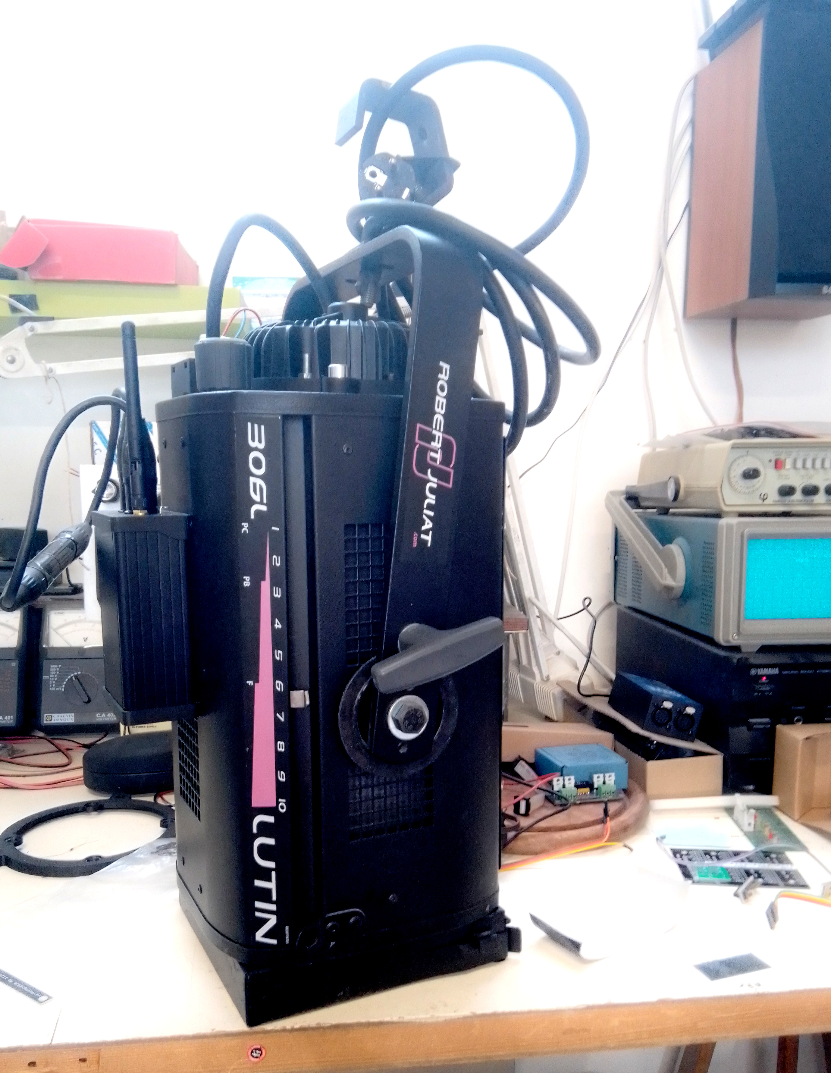
The RJ306 retrofit prototype has just taken its first breath.
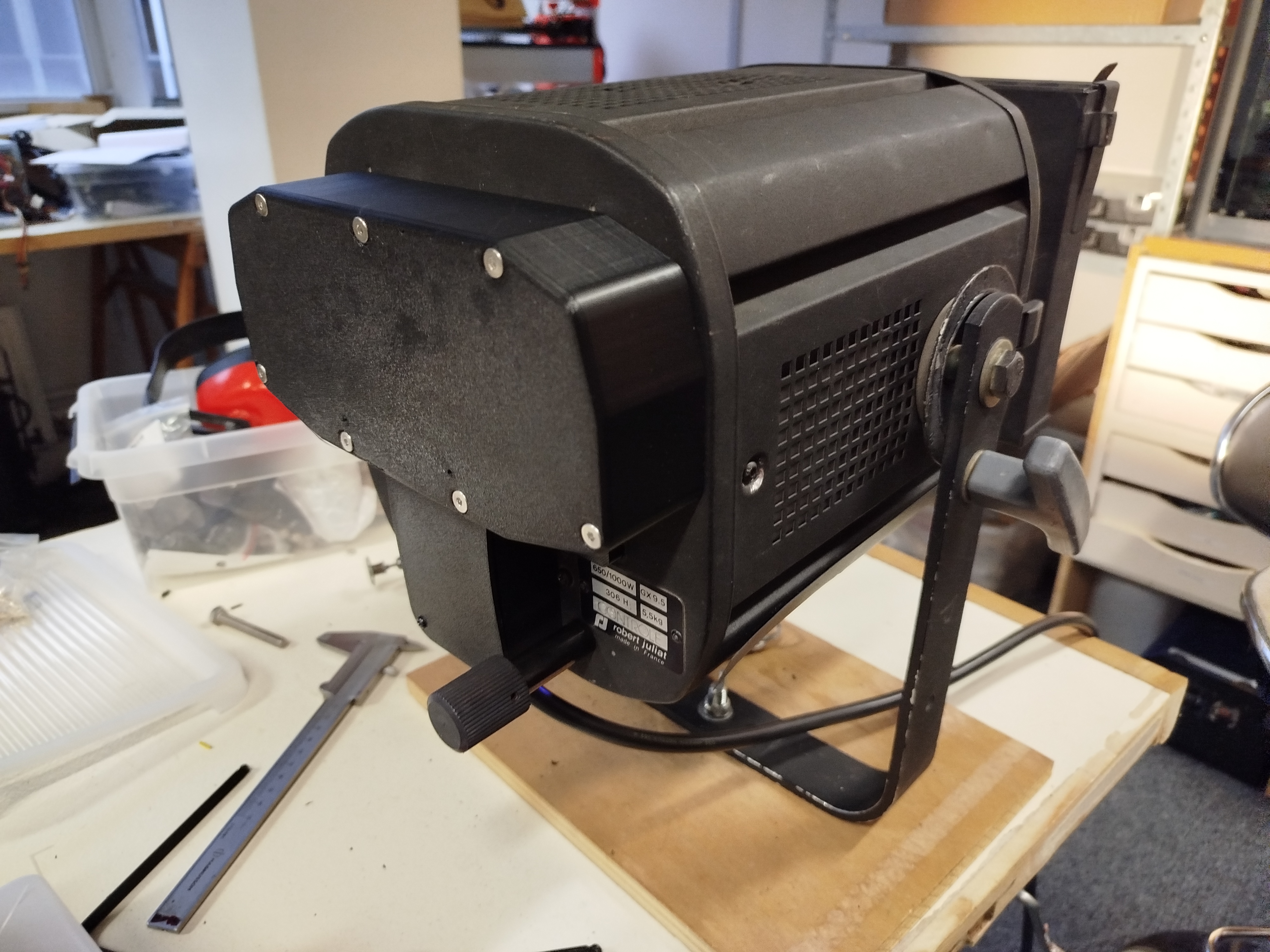
We will move on to more in-depth testing before tackling the methodology for creating the kits.
The next test subject will be the RJ310.
React on the Arpschuino forum or by email at arpschuino@gmx.fr.
January 17, 2026
Thank you to everyone who attended the presentation of our projector retrofit kits last Thursday at the Carreau du Temple.
And a special thanks to William for his very warm welcome.
If you couldn't make it, we plan to organize more events as soon as possible.
We were able to acquire 2 units of the Robert Juliat 310.
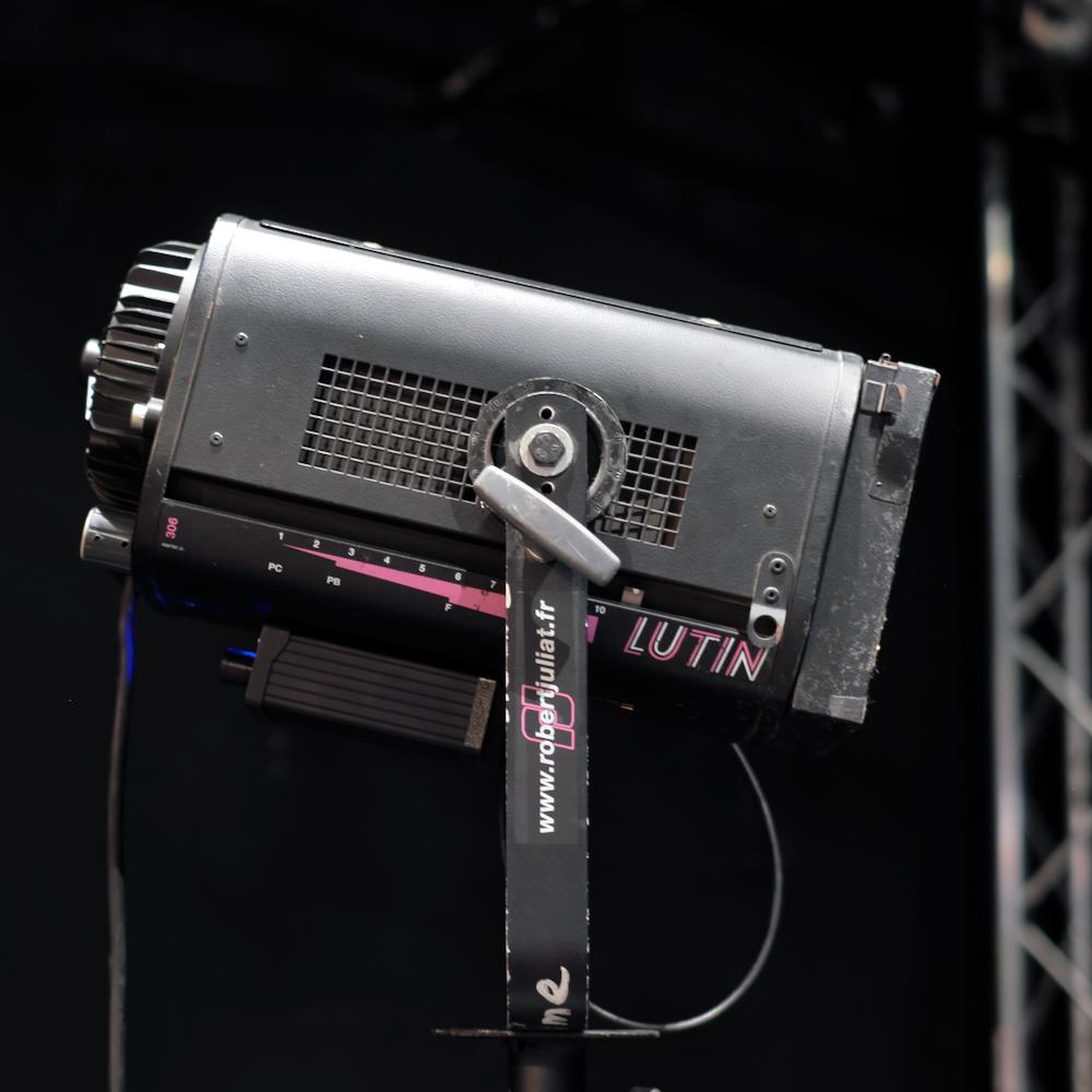
So now, at the workshop, in addition to the Lutin, we have the 306 and 310, and we are working on designing kits for these models.
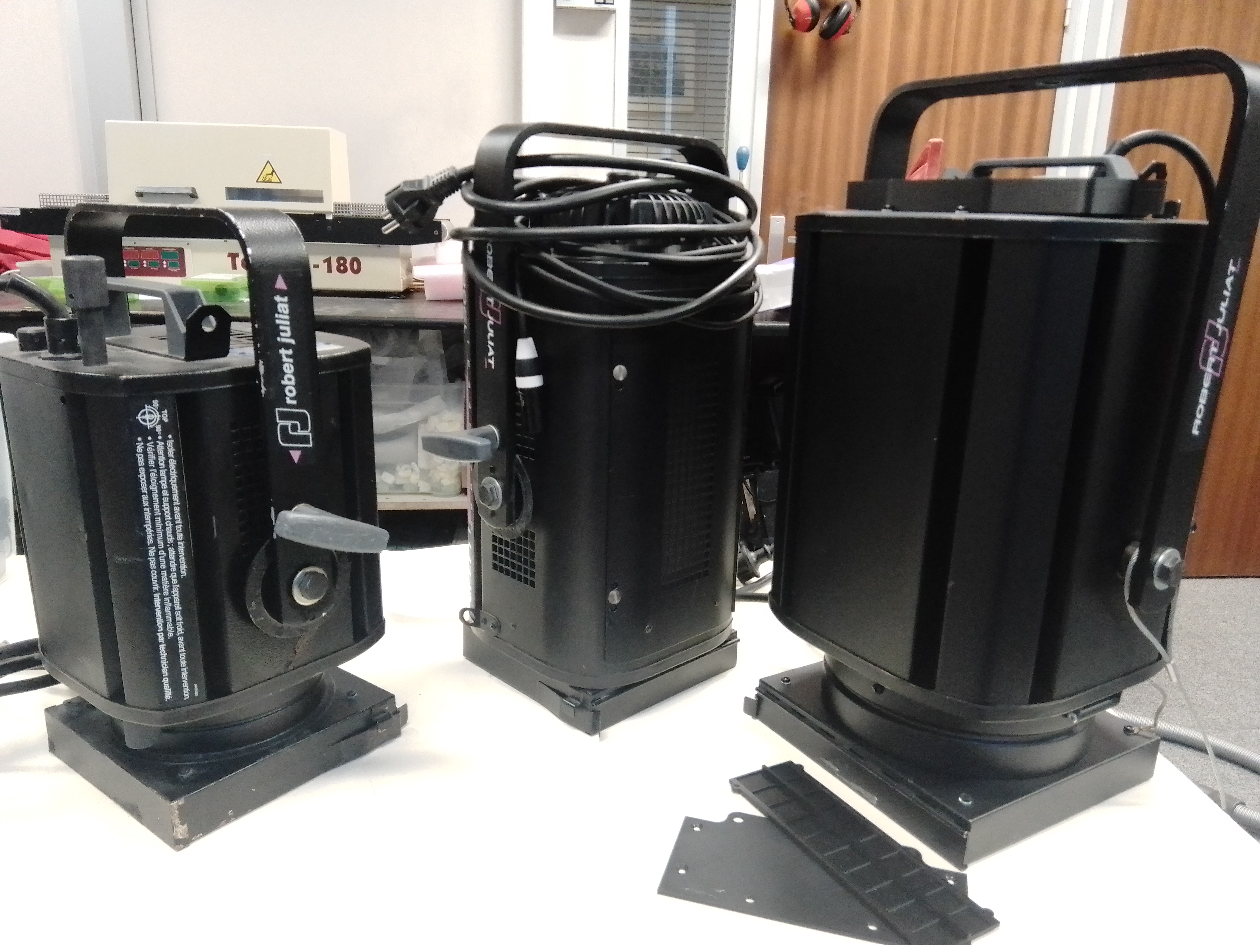
If you have other projector models in mind for retrofitting, please share them on the Arpschuino forum or by email at arpschuino@gmx.fr.
January 9, 2026
Presentation confirmed !
The presentation of our projector retrofit solution, initially scheduled for December 1, 2025 at the Carreau du Temple and later postponed due to venue availability,
will finally take place on January 15, 2026.
The event will still be held at the Carreau du Temple.
At the beginning of this new year, the whole team would like to send you its warmest wishes for 2026 — a bright, creative year full of inspiring projects and meaningful encounters.
We are very much looking forward to welcoming you in January to present our retrofit solution and to exchange ideas with you.
Thank you once again for your patience, support, and enthusiasm.
For any questions or registration requests, feel free to contact us via the
Arpschuino forum
or at arpschuino@gmx.fr.
November 19, 2025
Update – Presentation Postponed
The presentation of our projector retrofit solution, originally scheduled for December 1, 2025 at the Carreau du Temple, has been postponed to January 2026 due to venue availability.
It will still take place at the Carreau du Temple. We will share the new date as soon as it is confirmed!
Thank you for your patience and your enthusiasm for our retrofit solution.
For any questions or to register, you can contact us via the arpschuino forum or at arpschuino@gmx.fr
November 13, 2025
Following the success of our first presentation, we received very positive feedback on the light quality, power, and dimming capabilities of our projector retrofit solution.
For those who were unable to attend, we are pleased to invite you to a new presentation, which will take place in Paris, at Le Carreau du Temple, on Monday, December 1st, 2025, at 2:00 p.m.

This will be a great opportunity to (re)discover our technology in real conditions and to engage directly with our team.
To register, please contact us via the arpschuino forum or by email at arpschuino@gmx.fr .
october 11 2025
In our previous post, we announced a presentation of our theatre spotlight retrofit project.
This presentation will take place on October 21st in the morning, at the Berthelot Theatre in Montreuil, France.
If you would like to attend, please contact us via the arpschuino forum or by email (arpschuino@gmx.fr)
September 19, 2025
Retrofit launch!
This summer, we had the pleasure of delivering our very first retrofit kits to the Halle Roublot Theater in Fontenay-sous-Bois.

We would like to warmly thank Corentin and the entire Halle Roublot team for their support and trust.
A demonstration is scheduled soon in a theater in the Paris region.
For further information or to attend the event, please contact us via the Arpschuino forum or by email at: arpschuino@gmx.fr
January 1st, 2025
The arpschuino team wishes you a happy new year 2025.
September 27, 2024
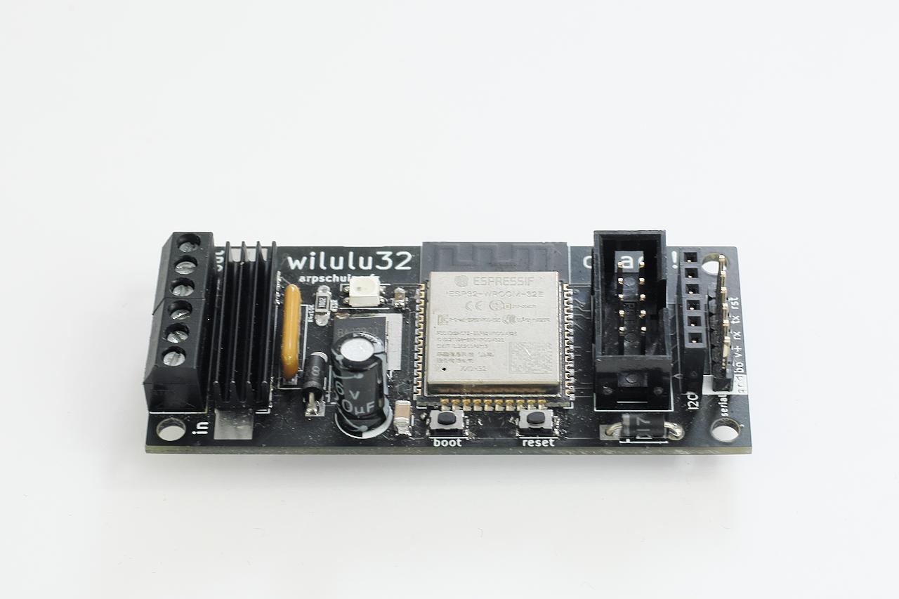
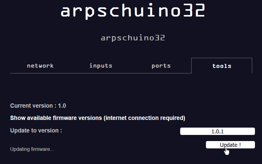
With the arrival of the wilulu32quad, the firmware evolves.
In the wilulu32 user interface, ports page, we must now select the type of wilulu32 used: single or quad.

This new version, 1.4 called Four Knights, brings a new feature,
the strobe mode:
once activated we will have for each LED, a circuit for the level (2 if you are in 16-bit mode) and an additional one for the strobe.
For now, it is the frequency that is controlled in DMX, tell us on the arpschuino forum
if you also need to adjust the pulse duration, and if this adjustment should be done from the user interface or via DMX.
Of course this new update also applies to the arpschuino32.
All details can be found in the release notes.
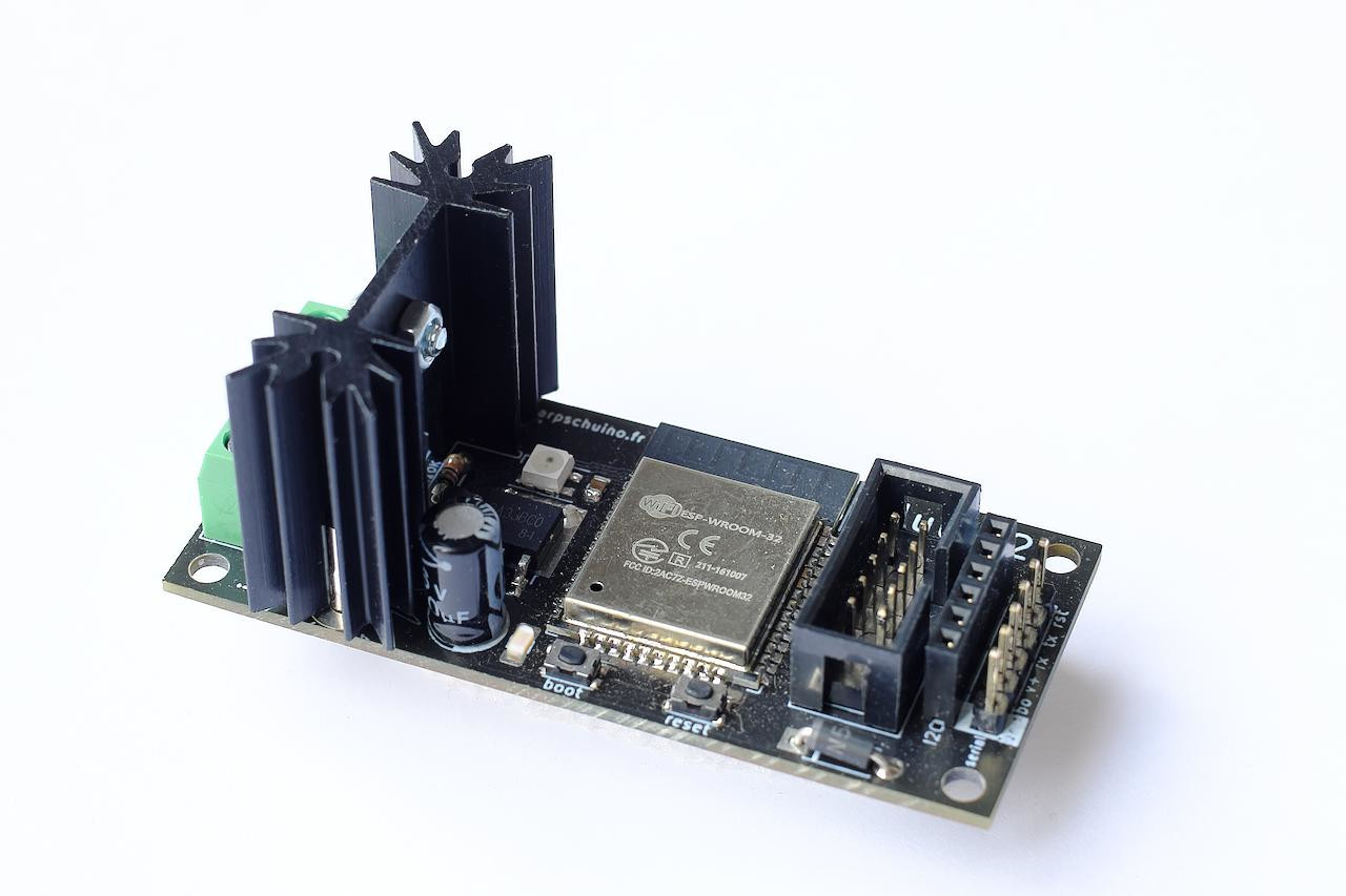
September 18, 2024
Fall 2022, we presented the arpschuino32, a huge leap forward from the arpschuino².
Fall 2023, it was the turn of the wilulu32.
Today we are pleased to introduce you to the wilulu32quad!
In a format identical to the standard Wilulu, we will benefit with this new board from no less than 4 circuits of 2.5 Amps each!
With this pocket dimmer, we will be able to control, in artnet WiFi, RGBW LEDs or 4 independent LEDs.
But that's not all, we are currently working on a projector retrofit project:
Our goal is to design halogen>LED conversion kits without any compromise on light quality, ergonomics and reliability.
If you are interested, do not hesitate to ask us questions and come and discuss it on the arpschuino forum.
Bonne rentrée !
July 20, 2024
It's the holidays! We can still be contacted, by email or on forum arpschuino, but don't expect an instant response.
We will be back around August 20.
Until then, have a good summer!
May 7, 2024
Hotfix: Here is a small firmware update for the arpschuino32 and wilulu32, which concerns arpdress board users.
Version 1.3.0.2 (Double fianchetto, fix)
We had a little problem, the arpdress board was no longer recognized in the latest versions. It's now fixed!
Release Notes
Update tutorial
Forum arpschuino
More important new features are coming.
March 4, 2024
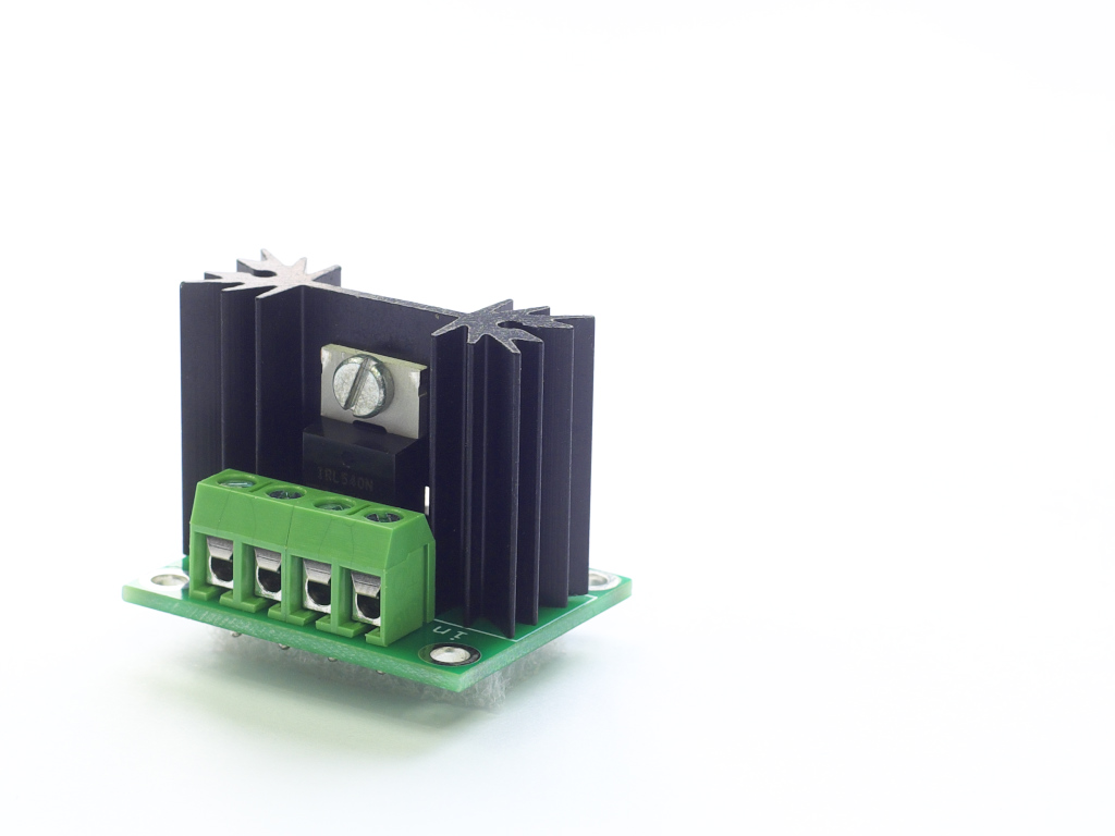
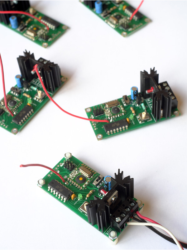
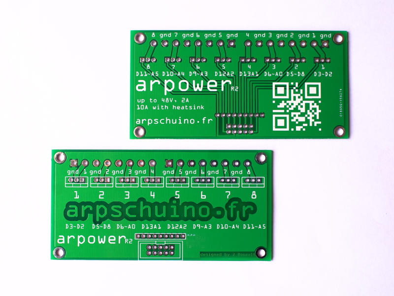
The arpower has been completely redesigned:
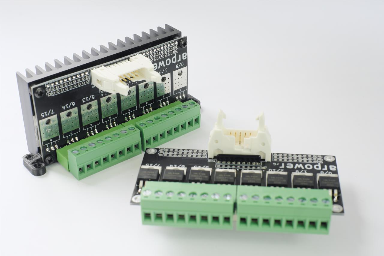
The new printed circuit contributes to heat dissipation, the maximum intensity per chanel without heatsink goes from 2 to 2.5 amps and 8 to 10 amps with heatsink.
For boards with a heatsink, we now have vertical mounting, for the benefit of compactness.
Note that we still have some old version arpowers left, we can sell them to you at a reduced price.
January 29, 2024
We hadn't yet published the wilulu32 source code, that's it!
We took the time to unify the codes of arpschuino32 and wilulu32.
This means that the two boards will evolve together, each advance of one will benefit the other.
This new version is called "double fianchetto" and has the number 1.3 for both boards.
January 1, 2024
We wish you a
December 10, 2023
The arpschuino32 is now available in kit version.
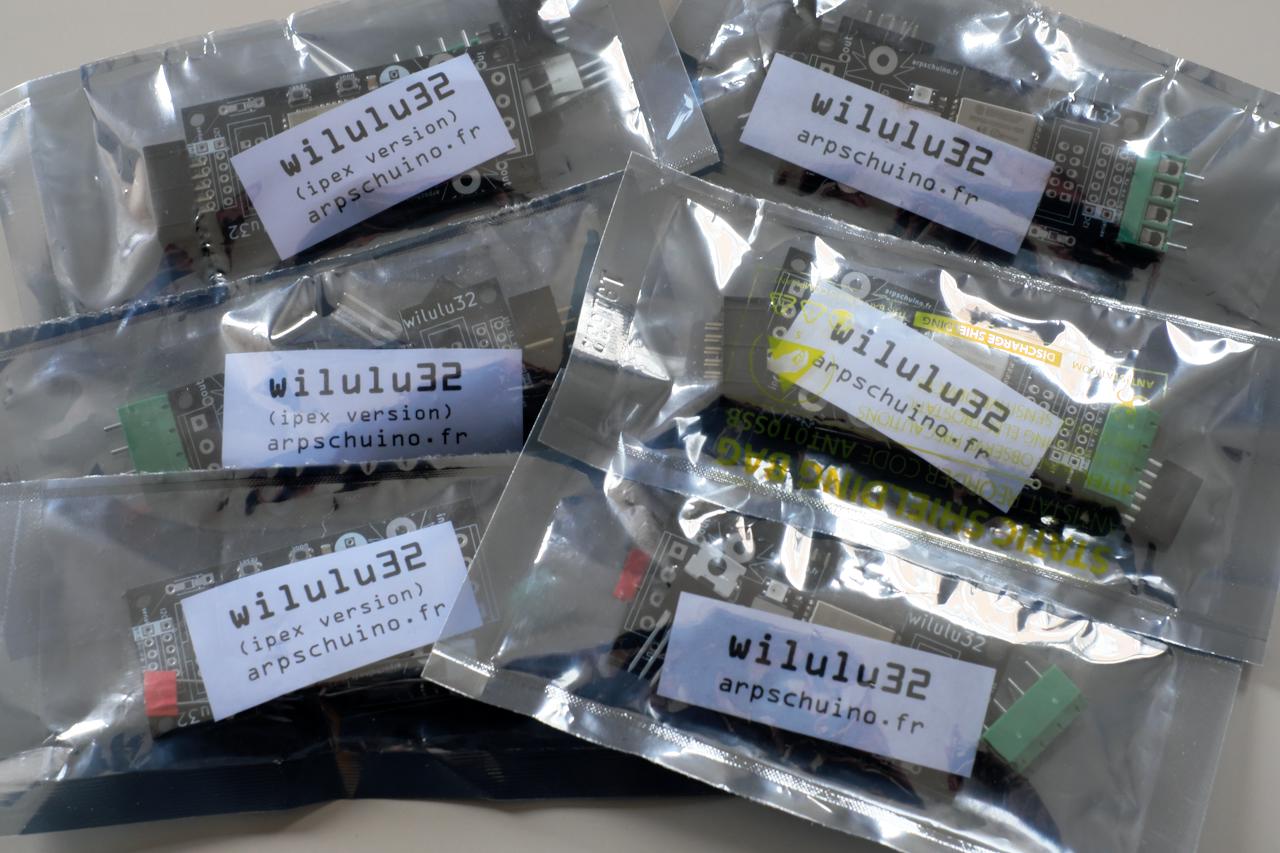
Like the arpschuino32, the wilulu32 was initially available in kit version only.
You may have noticed that new boards feature more and more SMD (surface mounted) components.
We assemble them in our workshop in Fontenay sous bois, using our reflow oven.
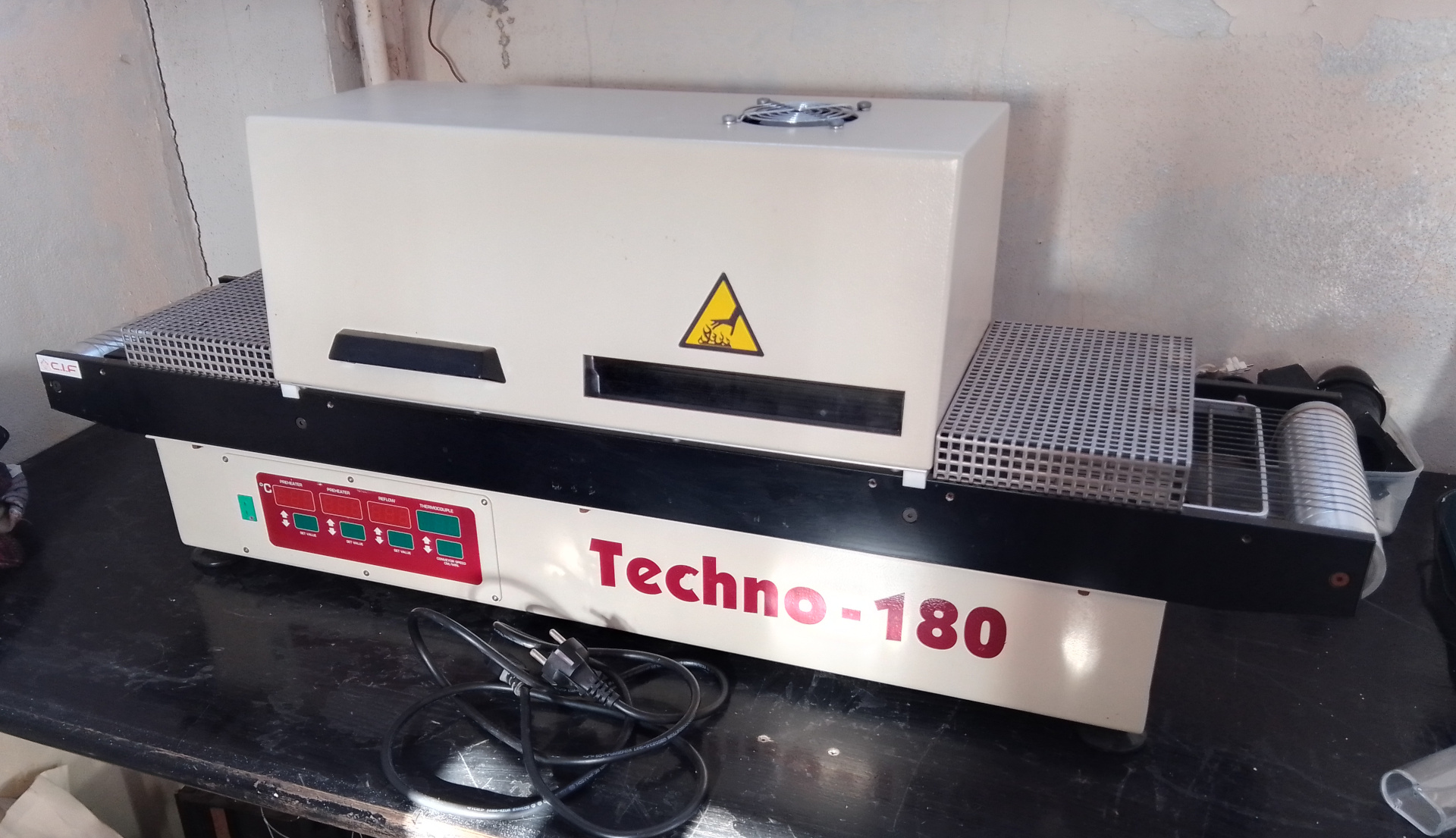
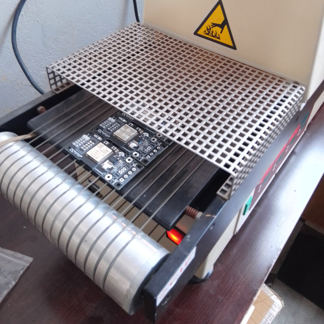
Delivering the first assembled series allowed us to test each of the pieces supplied to ensure the reliability of our welds.
It is therefore after conclusive tests that we offer you these kits, with many components already welded.
Choosing a cheaper kit version becomes even more interesting.
And as always, we are waiting for you to discuss it on the arpschuino forum.
October 17, 2023
Exactly one year ago, we presented the arpschuino32.
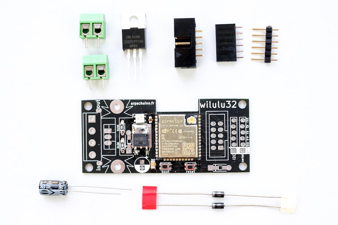
Today it is Wilulu's turn to be completely renewed. We are pleased to introduce wilulu32 to you:
Like the first generation wilulu, it is a pocket dimmer, but apart from that everything has changed!
Indeed, like the arpschuino32, it is built around an ESP32, and is therefore now controlled via artnet Wifi.
The radio link is significantly improved and a dedicated transmitter is no longer necessary.
But perhaps the most important change is the leap forward in PWM resolution.
From an 8-bit resolution (255 steps) that is unsatisfactory for LEDs, we jump to resolutions of 14 or 15 bits (32,767 steps!).
Another very important new feature: an 8 I/O port identical to those of the arpschuino32,,
which will allow us, without programming, to use all peripherals compatible with the Arpschuino, for motors for example.
And many other things: an I²C port, a multi-colored status LED...
Don't hesitate to come and discuss it with us on the arpschuino forum.
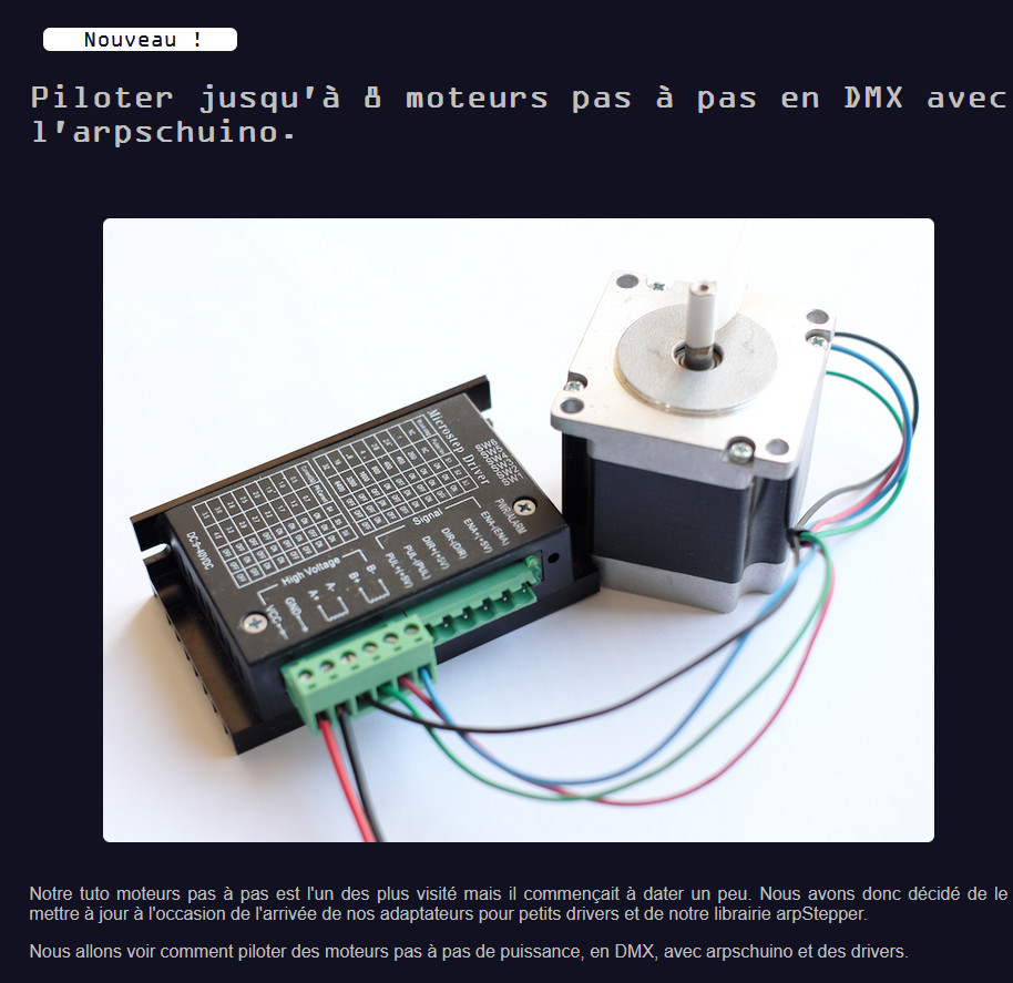
October 10, 2023
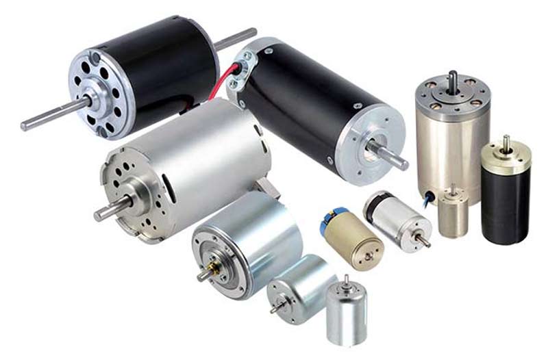
After our stepper and servomotor tutorials,
here is the last part of the trilogy: The DC motor tutorial (classic and brushless).
With the latest arpschuino32 firmware upgrade and support for limit switches, homing and many driver types,
it is the completion of a cycle devoted to motors.
With the set of software, hardware and documentary tools that we offer you, you should be able to control,
in DMX or Artnet WiFi, all kinds of motor-based applications for your shows.
If you have any comments or questions, as always, go to arpschuino forum!
Future development will be more focus on LEDs. An important new feature is in preparation and will arrive very soon!
August 25, 2023
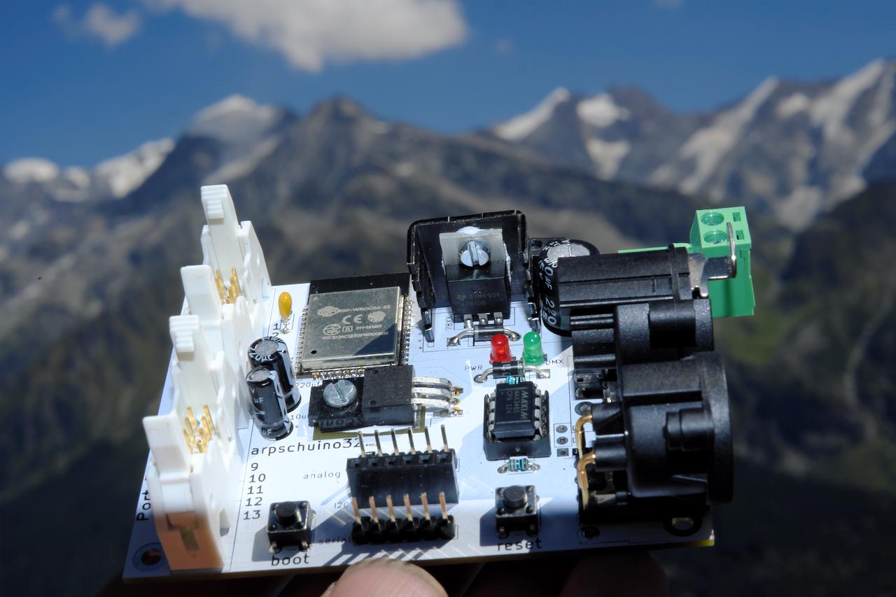
The holidays are finished !
A last look at the glaciers of the Italian Alps...

But, it looks like an intruder has slipped into the picture. novelty in perspective?
You can always ask us the question on the forum!
Good return to all.
July 14, 2023
We're going to take a little vacation!
One more week to finalize your orders, until Friday July 21. And we'll be back a month later on August 21.
Until then, we will continue to respond to your emails, probably at a slower pace, and of course the forum remains active.
Important novelties are in preparation for the fall.
Till then, have a good holiday.
June 30, 2023
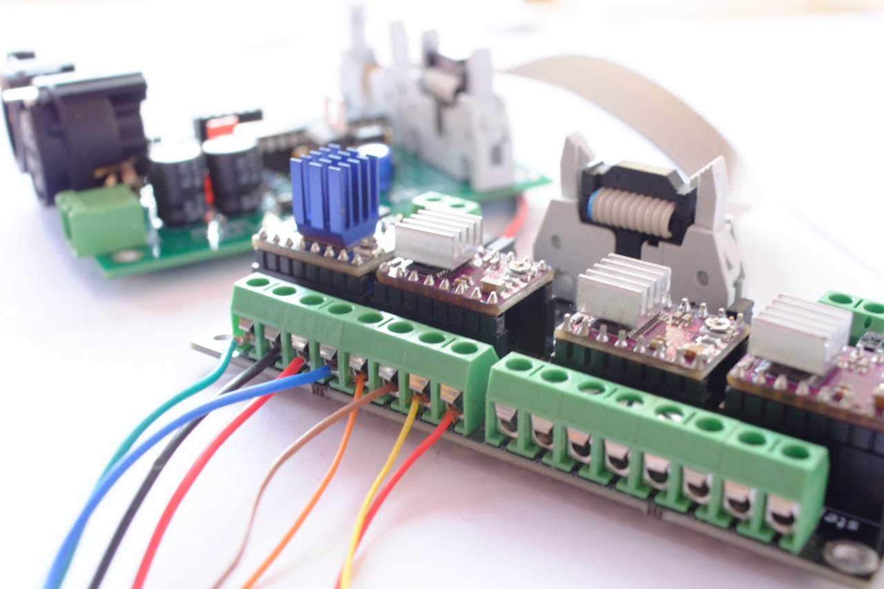
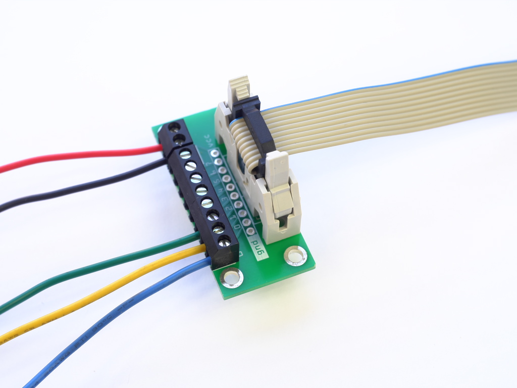
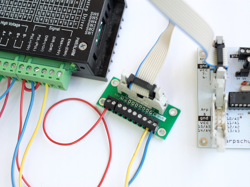
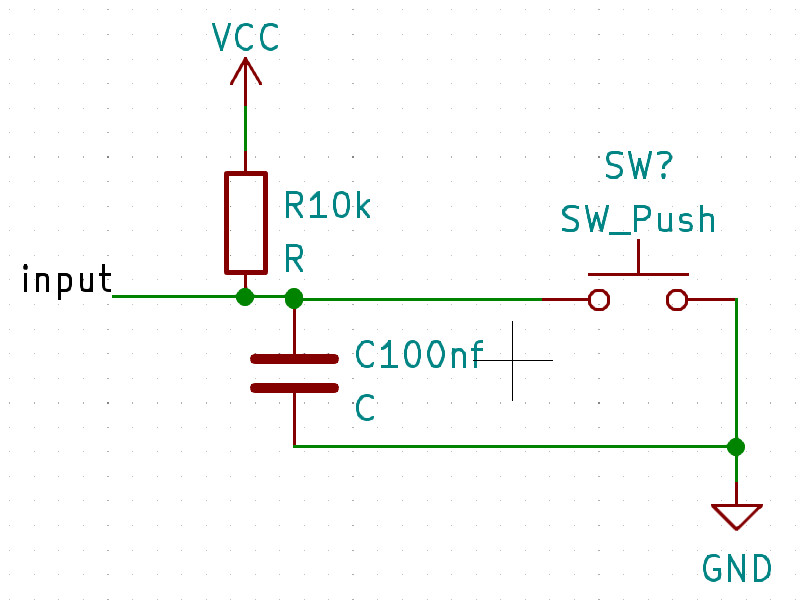
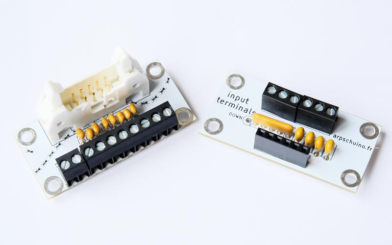
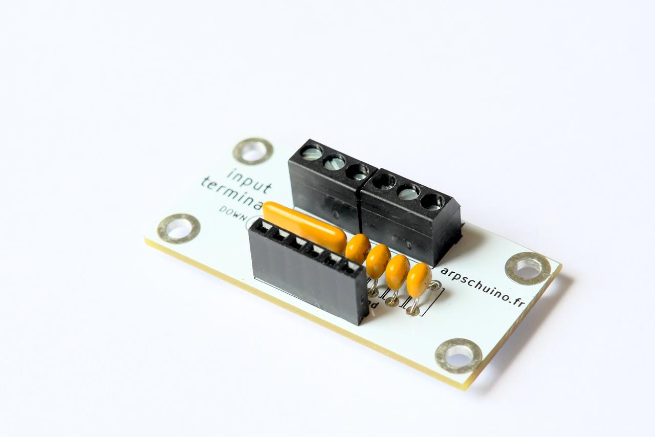
Here are two new little boards specially designed to simplify the use of limit switches, the arp>terminal-C:
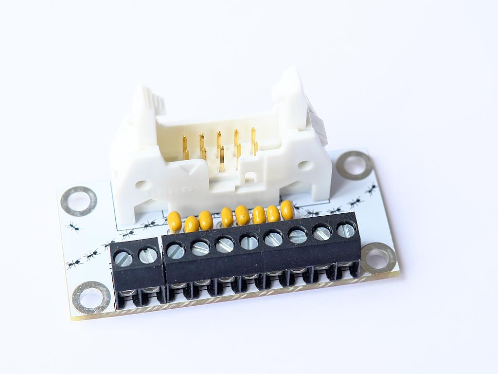
the input terminals:
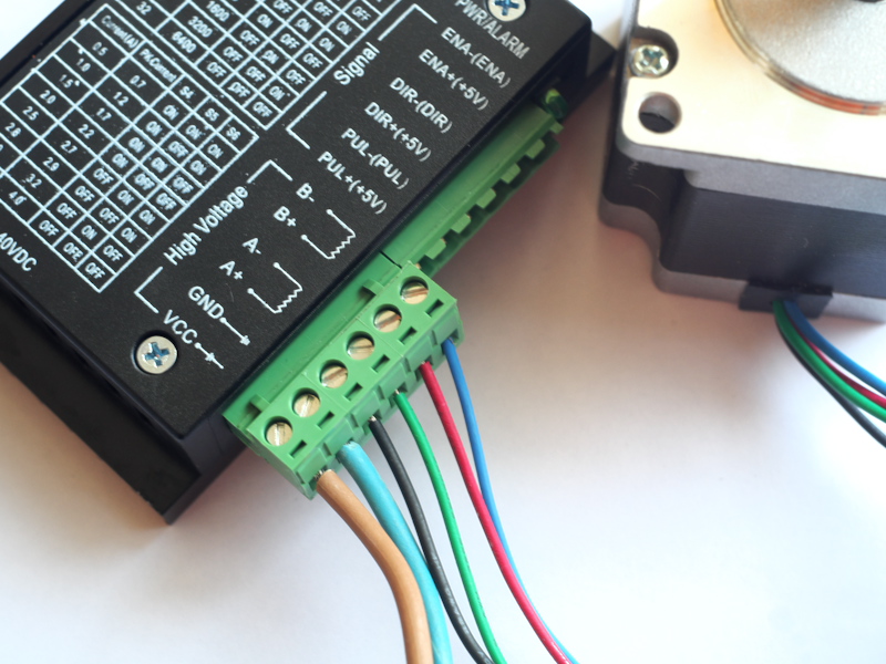
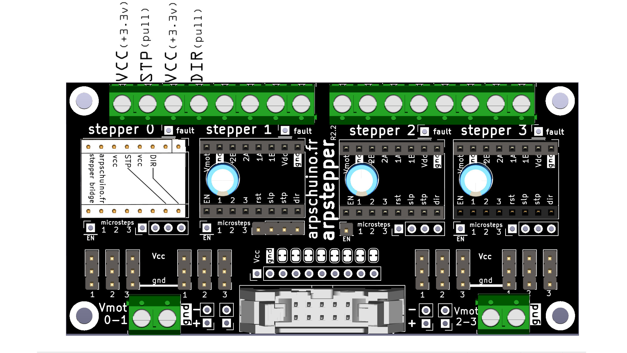
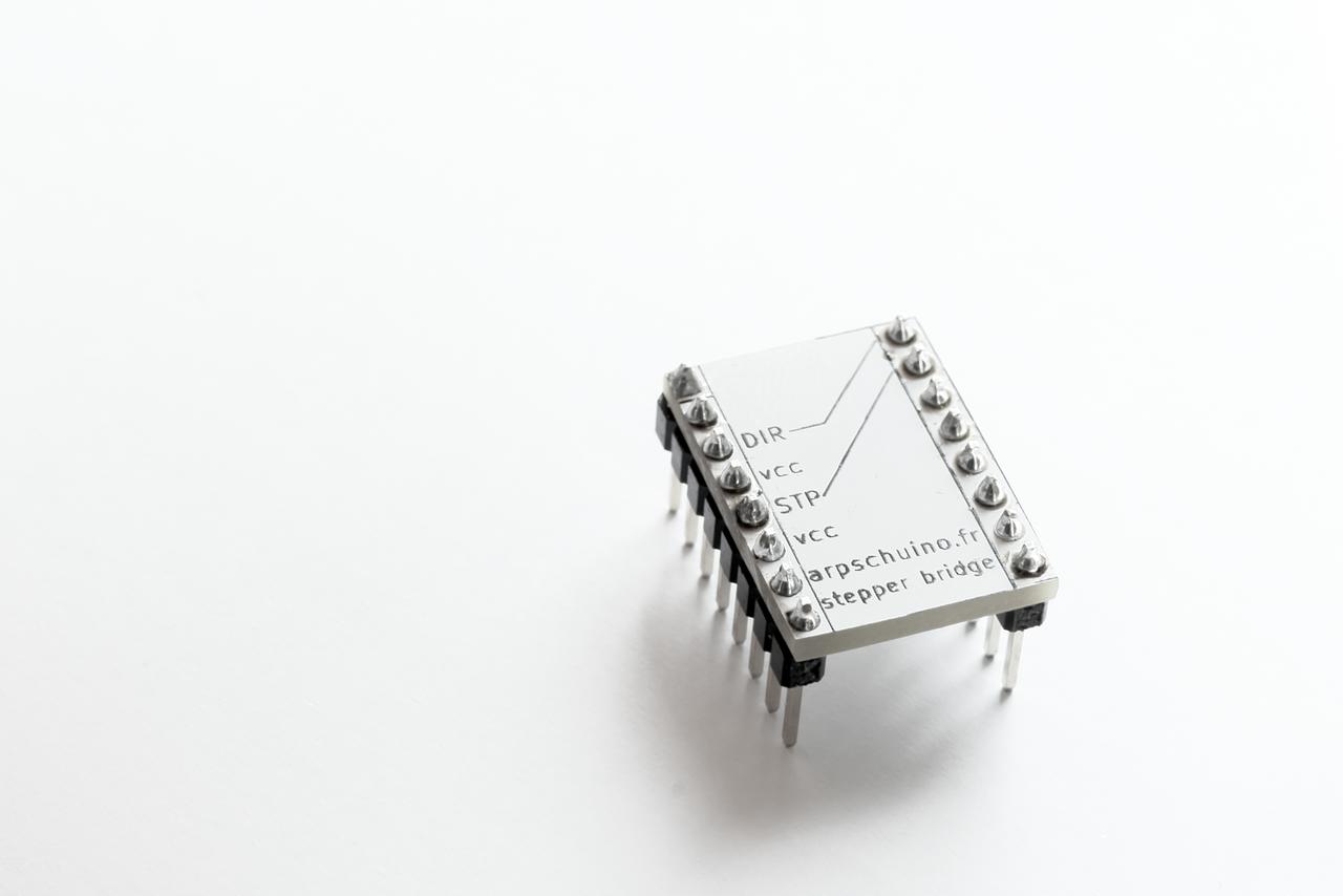
And that's not all! If you need to drive stepper motors with different types of drivers, here is the stepper bridge:
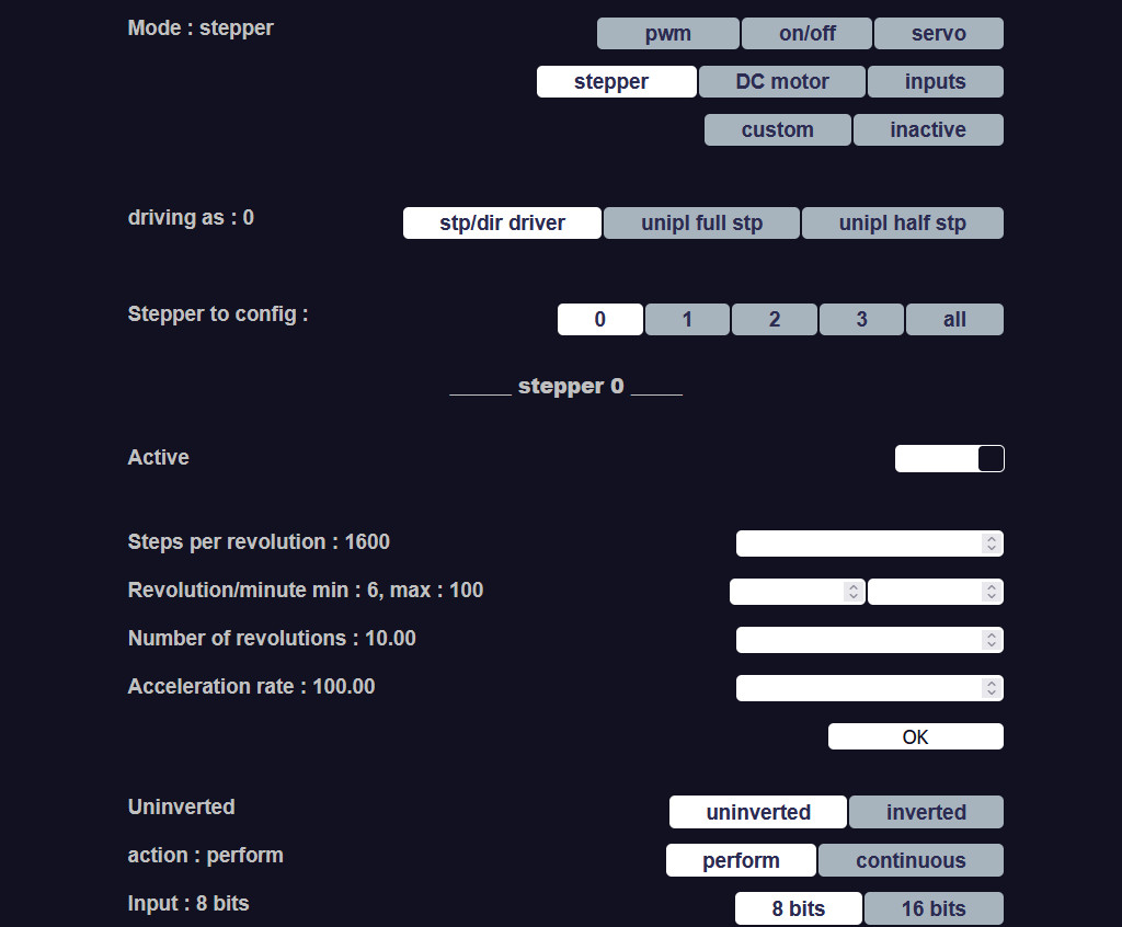
Our tuto stepper has been completely revised.
This update of course takes into account the arrival of these new boards, and of course the recent update Holy motors (1.2.3) from arpschuino32 firmware.
June 11, 2023
The new firmware version arpschuino32 (holy motors) is now fixed.
Goodbye version 1.2, now you have to download 1.2.3

Thanks to Thomas and Konrad for their precious help on the forum.
June 8, 2023
Warning, users have found errors in the latest arpschuino32 firmware (1.2).
Thanks to them for their vigilance!
It's happening on the forum.
This is being fixed.
May 26, 2023
holy motors!
This is the nickname of the brand new official version (1.2) of the arpschuino32 firmware
As its name suggests, it is mainly focused on motors, all types of motors: servo, brushless DC and stepper.
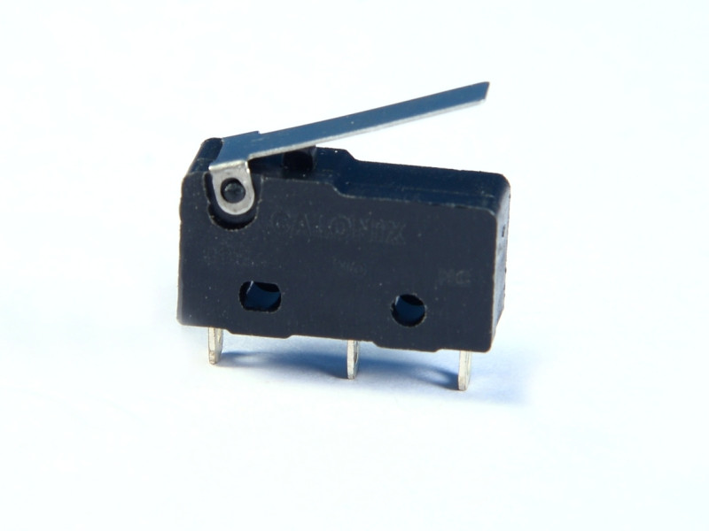
Some of you asked us for limit switches, homing, support for other types of drivers... We heard you!
You should also appreciate the new stepper motor speed and acceleration management, the difference is spectacular.
Some routers generated latency in Artnet, we have optimized the reception to correct this problem. A small debug, an improved display and that's it...
Details are in the firmware versions page.
The procedure to updateis in our tuto Update.
Do not hesitate to give us feedback on the arpschuino forum.
May 11, 2023
The official version (1.2) of the arpschuino32 firmware is almost ready, in the meantime here is a new version (1.1.8) in beta test.
On the menu, support for new types of motors and drivers, and more.
As always, it's happening on the arpschuino forum.
March 18, 2023
The evolution of the arpschuino32 firmware continues. No official release yet, but a new version (1.1.5) is now available in beta test.
Current development work is focused on motors, we know from your forum posts that some of you will be happy to learn
that to the new management of speed and acceleration already present in the last beta, we added the management of limit switches
as well as a homing system at start for stepper motors.

Do not hesitate to make this update (reversible) to version 1.1.5
and give us feedback on the arpschuino forum.
February 13, 2023
After the very recent arpschuino32 firmware update, the evolution continues!
If you wish, you can participate in these advancements and test the latest features and improvements.
The beta-tested versions are in principle already relatively stable, you can anyway go back at any time.
It's happening on the arpschuino forum.
We look forward to your feedback, suggestions etc...
February 6, 2023
After the update of the arpschuino core (for arpschuino², tinylulu, twinylulu, arpsensors etc...), here is now an update of the arpschuino32 firmware.
I2C port support is coming. The arpschuino32 is now natively able to drive tinylulus, twinylulus, arpsensors and spider boards.
An I2C scan is possible from the arpschuino32 configuration interface, allowing you to easily identify the addresses of the I2C modules present.
And since many of you on the forum are asking for limit switches and a homing system for motors,
we have included two examples in the "custom_port" part of the source code.
Add to that a little optimization and debugging, and here is the new version 1.1! Details are here.
The update is very simple and risk-free, the procedure is in our tuto Update.
A tutorial on how the I2C port works and on the custom port are in preparation, but in the meantime do not hesitate to ask us questions on the arpschuino forum.
January 25, 2023
With the arrival of the tinylulu and the twinylulu,
an update of the arpschuino core was necessary.
Update details are here
To update, follow the instructions in this tutorial.
Attention, this update and the arpschuino core in general do not concern the arpschuino32.
The arpschuino32 firmware should also benefit from an update, very soon.
We talk about it on the forum arpschuino?
January 21, 2023
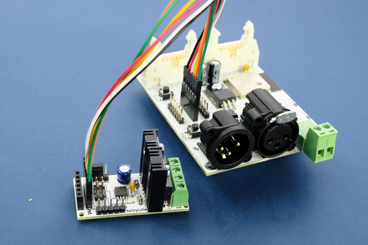
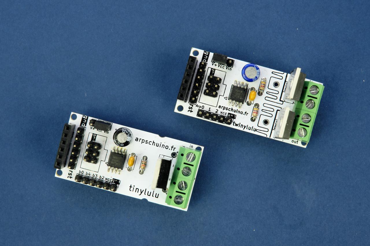
Here are not one but two new boards: the tinylulu and the twinylulu !
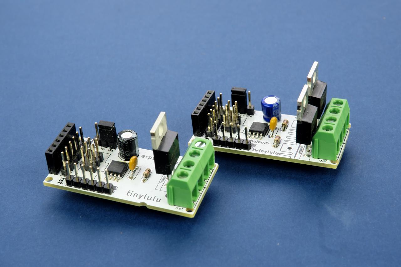
These are small stand-alone dimmers, one and two channel respectively.
The dimming is of course a fine dimming, in 12 bits, suitable for powerful LEDs.
They are equipped with inputs/outputs, including 3 analog inputs for the tinylulu, 2 for the twinylulu;
which allows them to be controlled with potentiometers or any kind of analog sensors.
They also have an ISP programming port and an I2C port, but we'll talk about that soon...
January 13, 2023
Small arpschuino32 firmware fix!
Details are here.
This is an opportunity to publish a short tutorial about firmware update..
2 janvier 2023
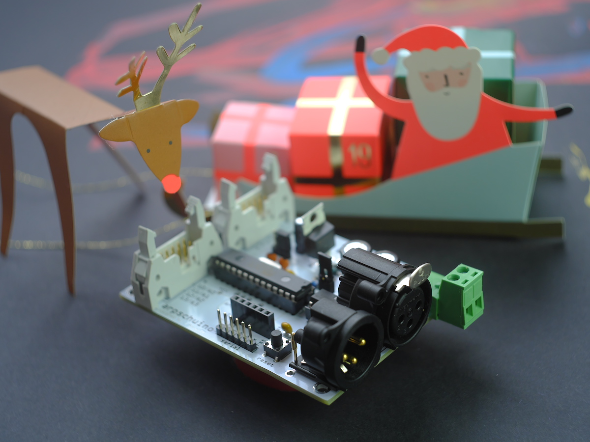
December 23, 2022
there are some funny decorations on the chrismas trees this year!
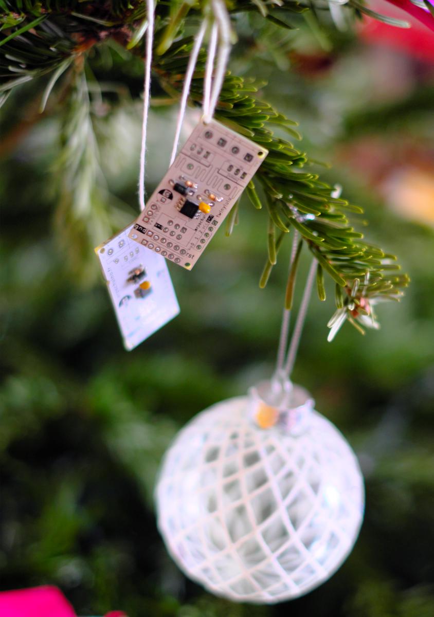
Any news coming up?
Do not hesitate to ask us questions on the forum arpschuino.
December 15, 2022
We will be speaking this Friday 16 at the National School of Theater Arts and Techniques (ENSATT)
for a meeting around the Creators and craftsmen of the technological transitions of the scene.
Admission is free and we will pass at 12.
Do not hesitate to come, sorry to warn you only at the last moment...
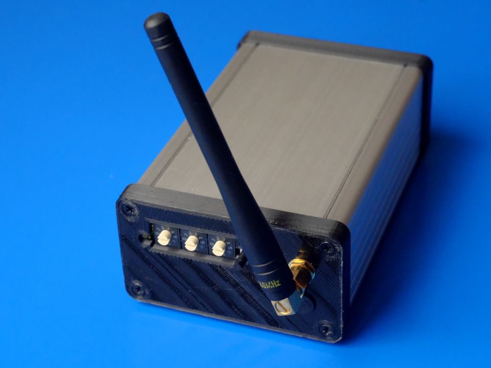
November 26, 2022
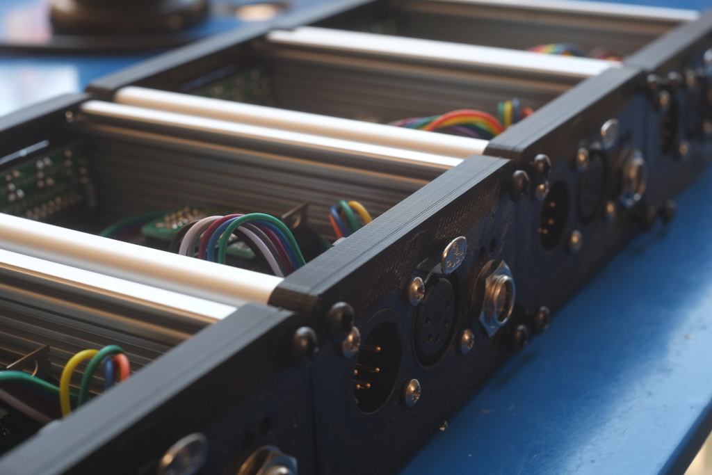
The arpschuino32 is now available in kit version.
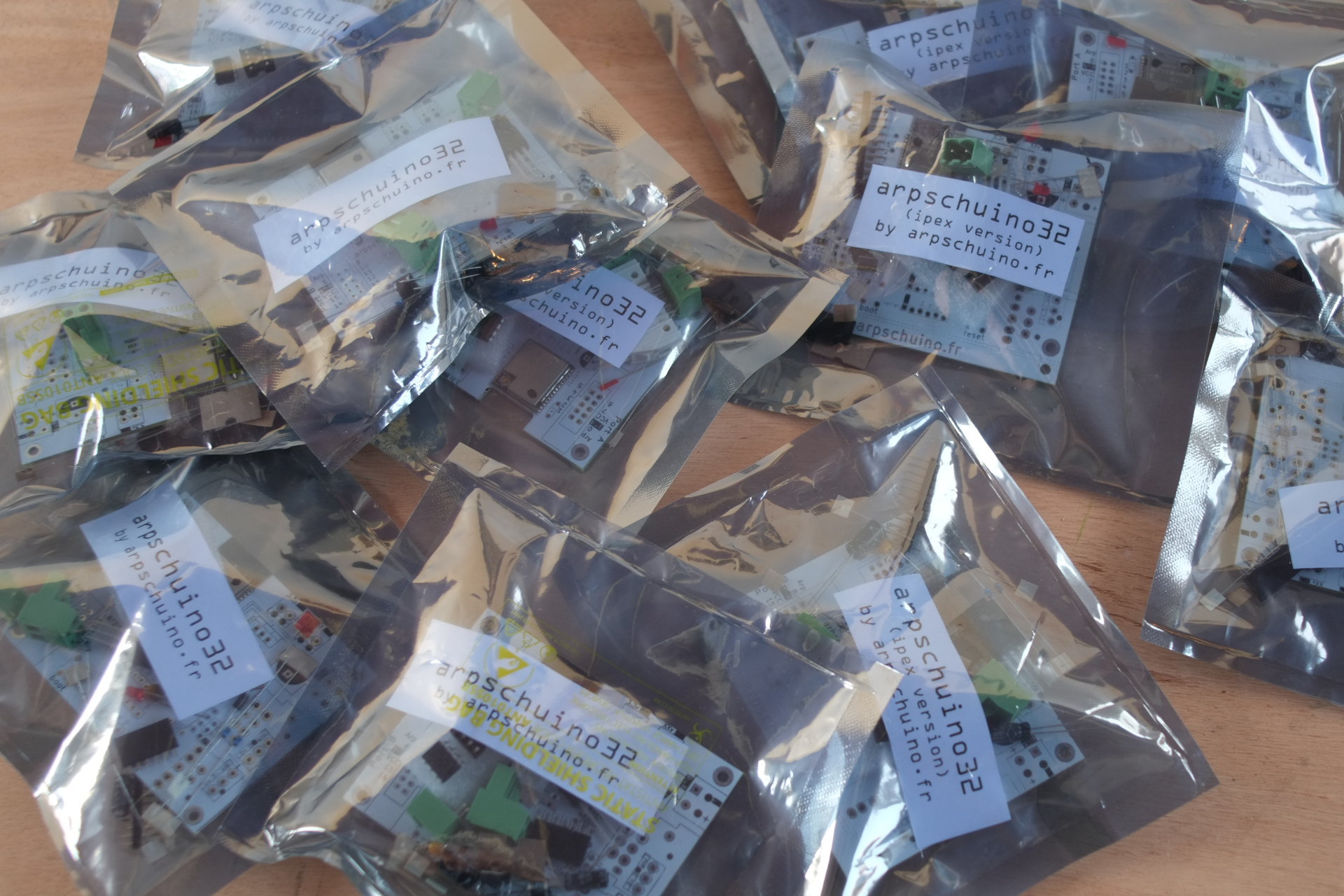
As for the assembled version, 2 possible options: with integrated antenna or ipex connector for external antenna.
When ordering, don't forget to specify whether you want XLR3 or 5 and pre-regulation or not.
See you soon on the forum arpschuino.
October 29, 2022
The new arpschuino32 is backward compatible with most boards in the arpschuino system.
Here are 3 updated tutorials for the arpschuino32:
relays,
servo motors
et steppers.
The arpschuino has a native wifi system, so RF12-based boards, such as the arpRF, are no longer compatible.
As for the boards using the I2C protocol, such as the arpsensors ou la spider board, they should be with the next firmware update.
And as usual, for questions, go to the arpschuino forum.
October 17, 2022
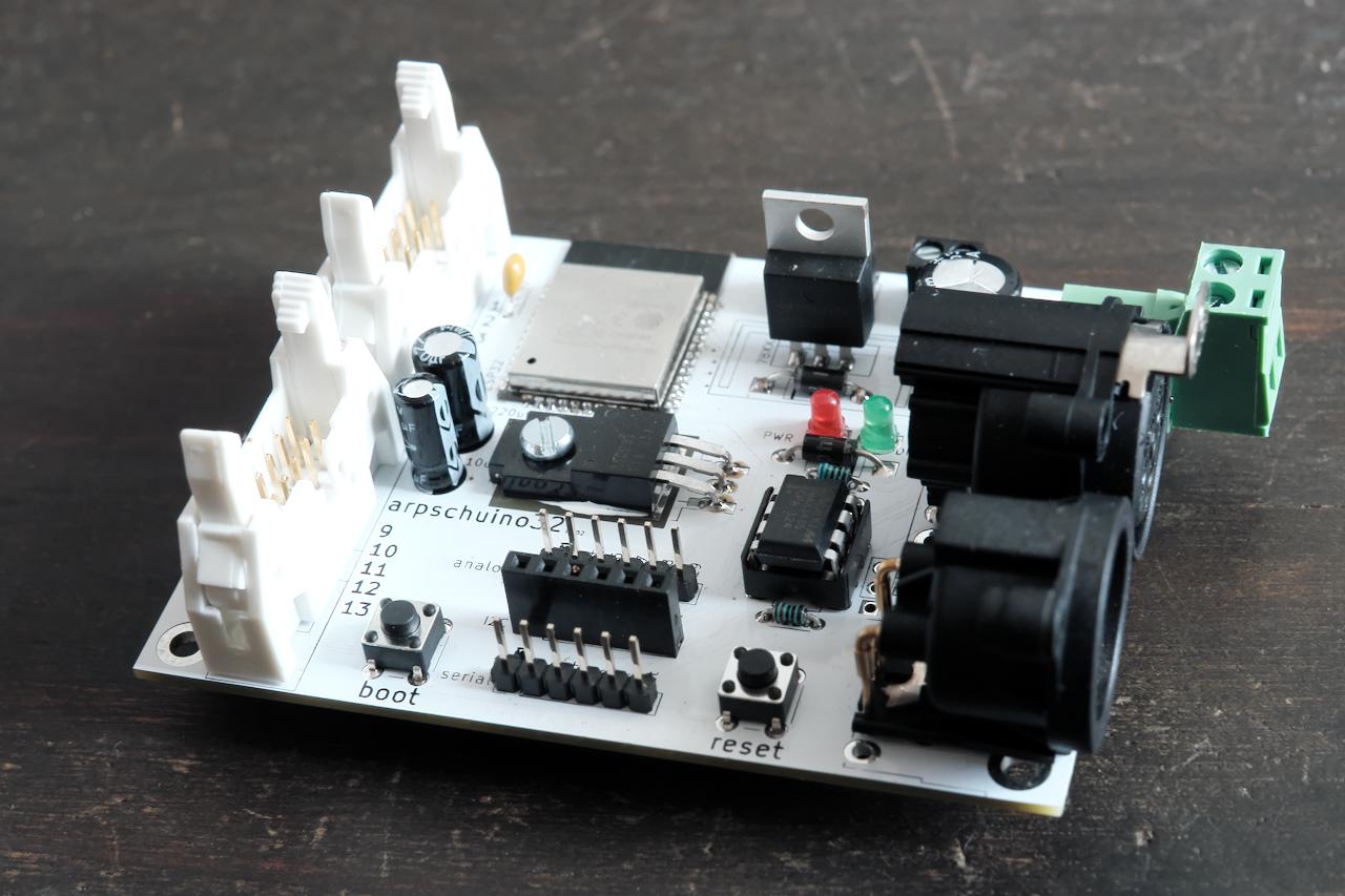
It's ready!
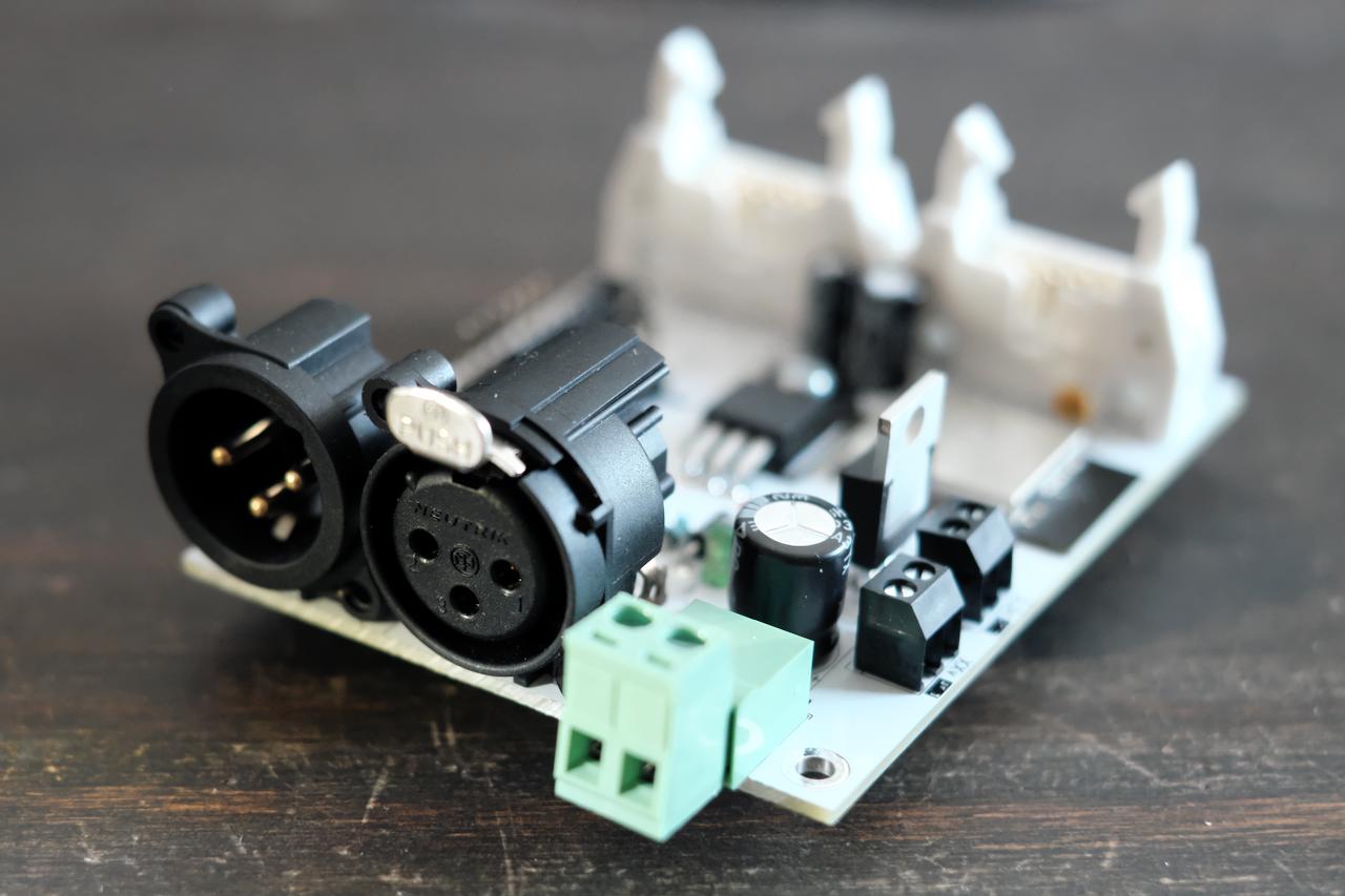
Our new arpschuino32 is now available.
Taking advantage of the power of the ESP32 microcontroller, wifi (artnet)
and accessible remotely thanks to an embedded server, you can
configure it entirely using a simple browser such as Firefox or Chrome.
With a greatly improved dimming capacity compared to the arpschuino²,
controllable in both 8bit and 16bit, this brand new
generation of boards remains compatible with the peripherals
existing ones like the arpower or the arpstepper.
Do not hesitate to ask us questions on the forum arpschuino.
September 28 2022
Come see us at our studio!
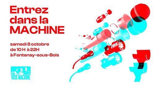
Open house with the Voix Machine collective, Saturday October 8 at our studio at 9 Rue des Mocards, 94120 Fontenay-sous-Bois, France
We hope to see many of you there.
It's also an opportunity for us to celebrate the release and introduce you to a preview of our new arpschuino32.
September 10 2022
Hello everyone
Observers again encountered this strange map in the Alps. One of them managed to get close enough without scaring the wild beast and gives us a much more precise shot of the mysterious object.
We are thinking of capturing it and presenting it to the public from October 7th to 9th in our studio in Fontenay (France), as part of an open studio event organized by the Voix Machine collective.
You can enjoy exhibitions by artists from the collective, as well as the presence of members of the arpschuino team. We will be happy to meet you at this event.
In the meantime, feel free to join our discussion forum, whether to present your projects, discuss electronics in general, arpschuino in particular and discussing about our new baby.
August 18 2022
We meet stranges arpschuinos in the french Alps :

Curious ? Ask us some questions on the arpschuino forum !
Happy end of the holidays or happy back to business everyone!
July 25, 2022
We're going to take a little vacation!
We are taking orders until the end of the week (July 29), then we will resume on August 22.
During this period, you can still place an order, we will be less responsive but we will answer you.
Of course the arpschuino forum remains open.
Happy Holidays to all !
Jully 8 2022
We are living in a somewhat complicated period, especially for electronics!
Many components are out of stock, with restocking times of sometimes a year and a half, and for others it's soaring prices...
Unfortunately, we will have to increase our rates a little next september.
Note that since February 2015, we had maintained our rates without any increase.
We will let you know the exact date, it will be in September, but all orders placed before will of course be billed at the current price.
Some boards might be unavailable in the future because of critical components out of stocks,
we're taking care to maintain our stocks and increase supply sources trying to avoid this.
On the good news side, we are preparing a big novelty in the next fall.
Do not hesitate to join us on the arpschuino forum to discuss all this. We wish you a great summer.
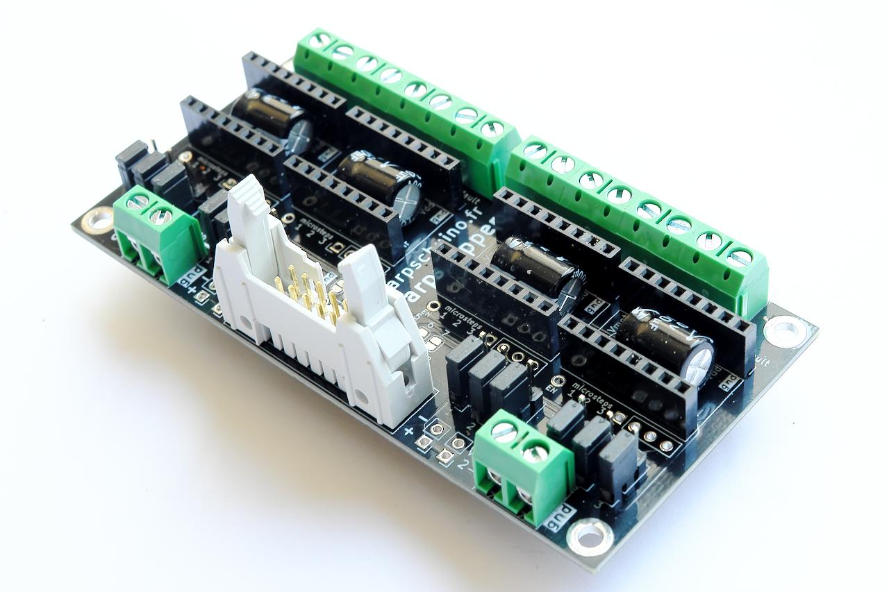
April 2, 2022
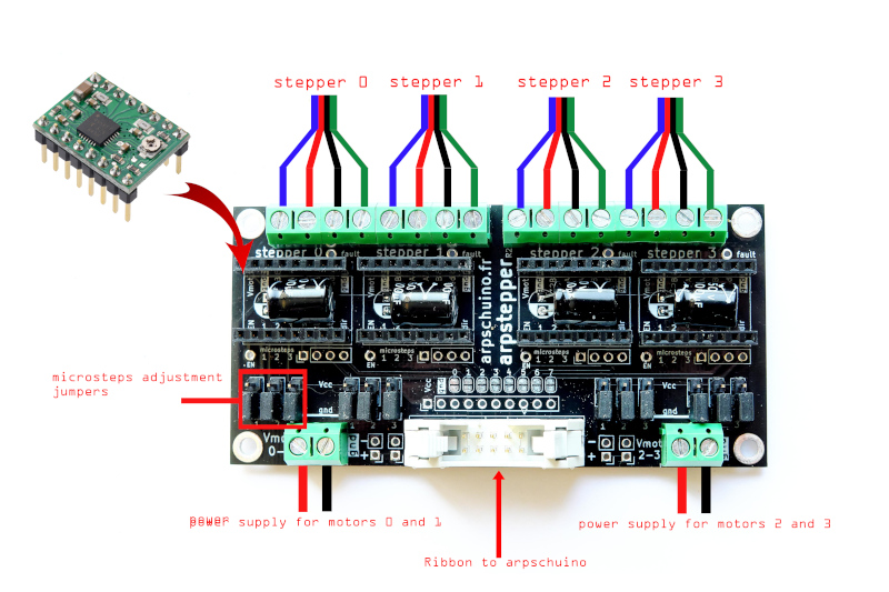
Here is a new version of the arpstepper:
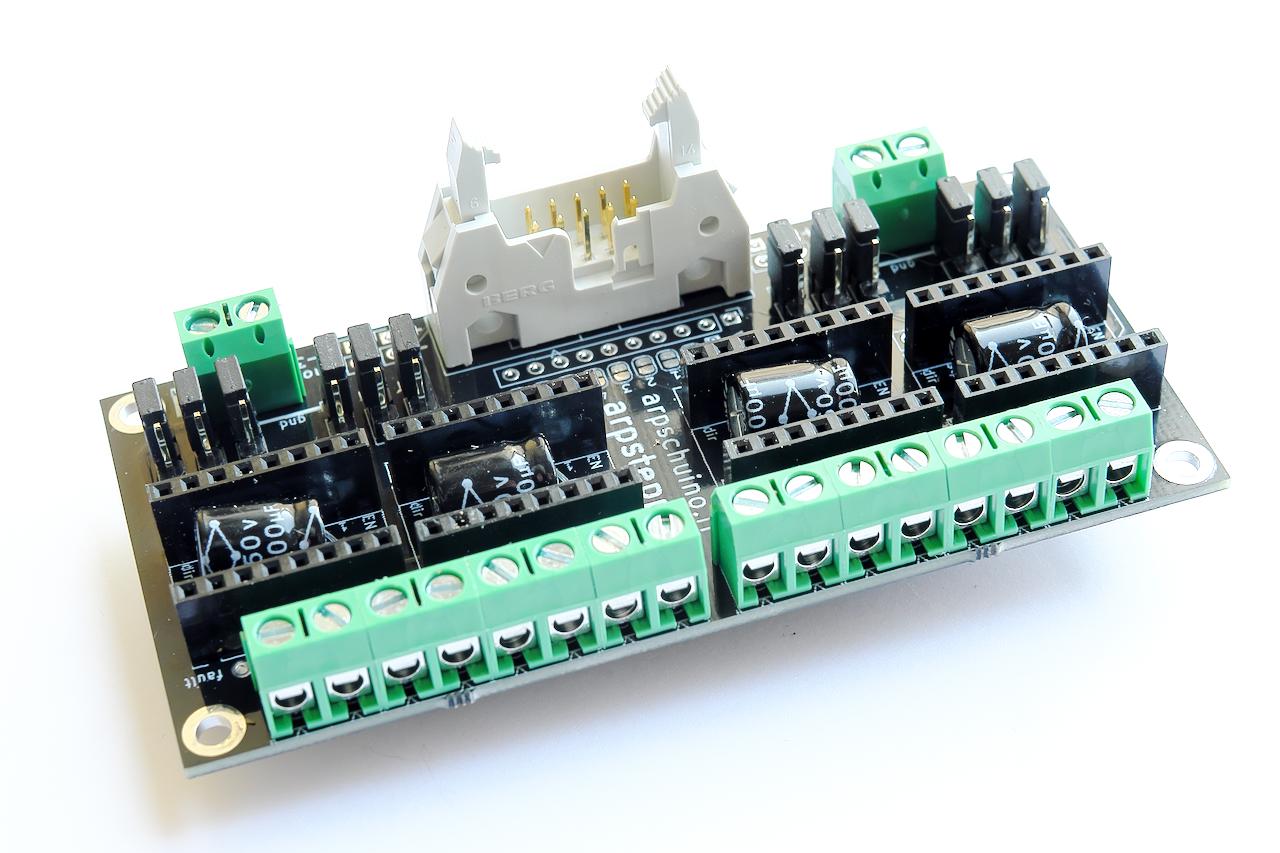
It's not just the color that changes:
there are now 4 100uf/50v capacitors instead of 2 100uf/35V
for better stability and the possibility of powering motors up to 48v.
The solder jumpers are now under the board and are closed by default.
No more need for a solder bridge for standard configurations.
Our tuto_stepper has also been revised to include silent drivers TMC2208.

March 24, 2022
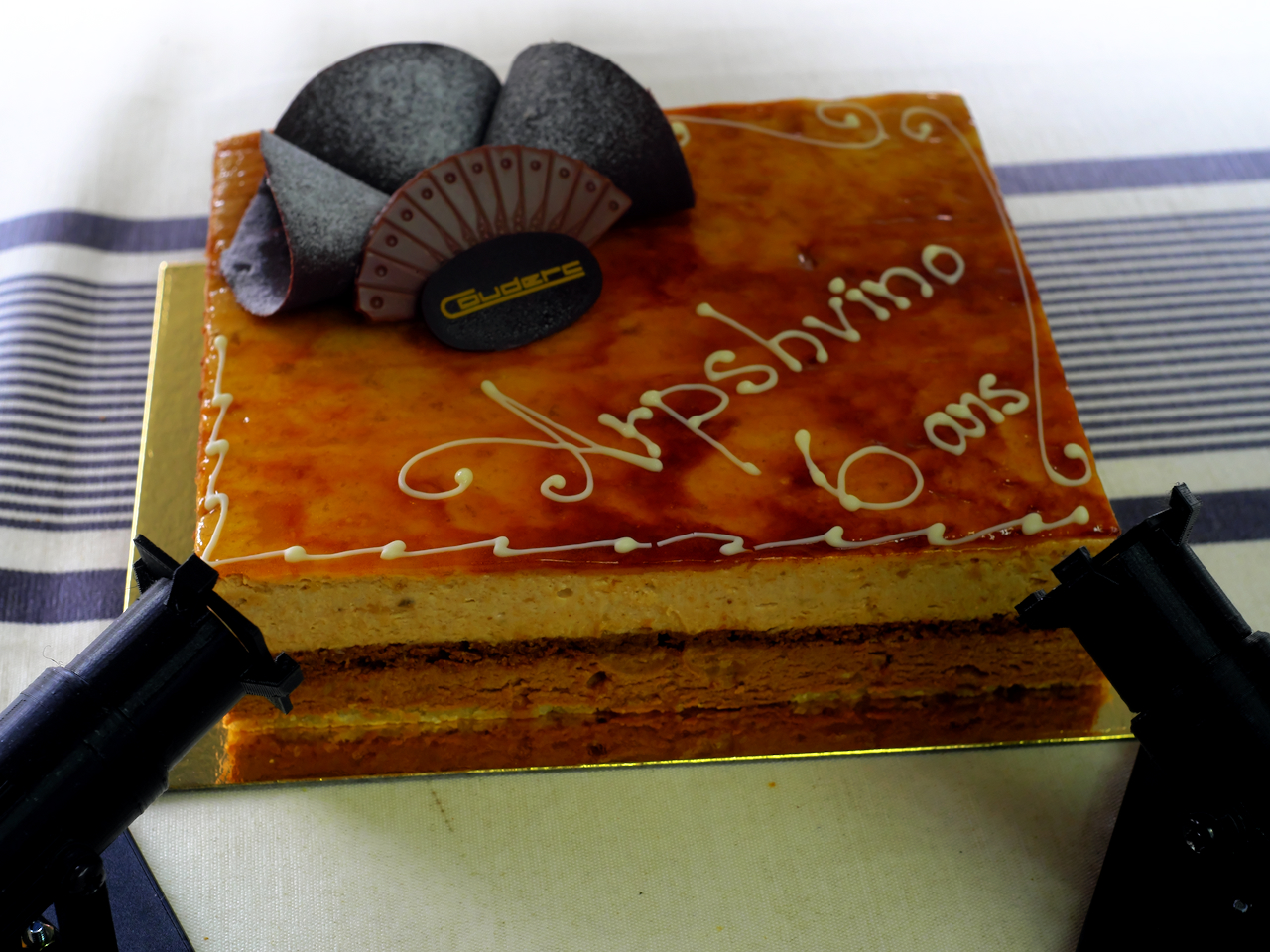
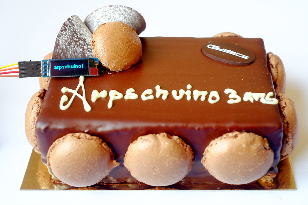
7 years old, the age of reason!
And a beautiful cake to celebrate, like every year.
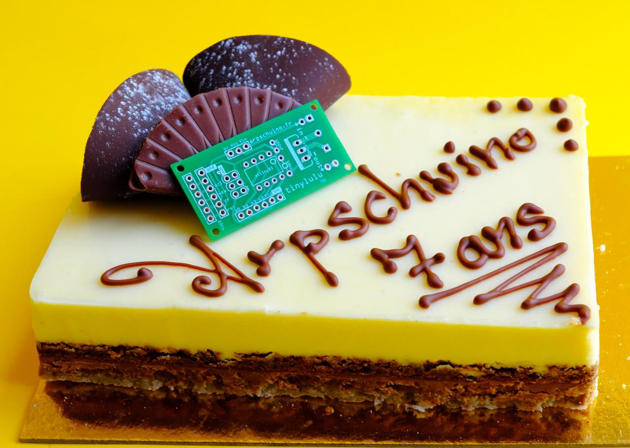
March 9, 2022
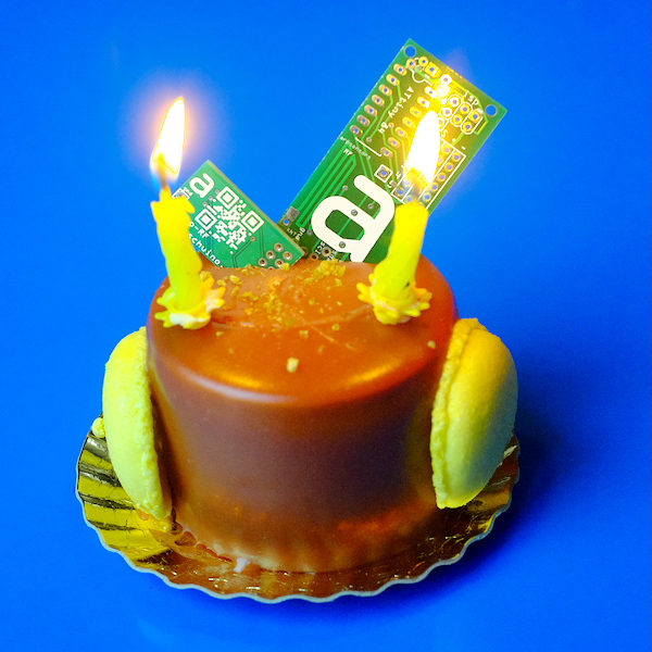
On February 27, arpschuino turned 7 !
We haven't lit the candles yet this year, but we'll celebrate a little late.

Thank you to everyone who has trusted us over the past 7 years.
February 18 2022
The arpschuino core has just been updated.
Main novelty, the softwareServo library which allows the use of servomotors with the attinys, therefore with the arpsensors.
Update details are here
To update, follow the instructions in this tutorial .
January 1 2022
We wish you a
If you like the photo, take a look at the examples section.
November 12 2021
Well, we haven't given any news for a while...
We are pleased to announce the opening of the arpschuino forum.
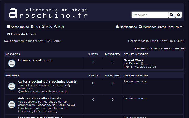
We hope to see many of you there, it is an opportunity to discuss with us and with other users.
Do not hesitate to subscribe, even if this forum is mainly in French, you can post in English.
July 27, 2021
This year, arpschuino is taking his vacation in August.
See you in September, until then we wish you a good summer.
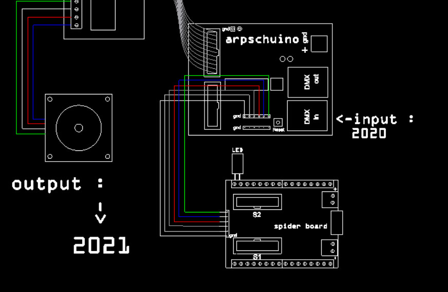
May 17 2021
New update of the core arpschuino, an error in the previous version wont let the examples of library arpstepper compile.
To forgive us, we added an example of DMX control for pixel led, in the examples of the Neo Pixel lib.
Details of the different versions of the arpschuino core are here.
To update, follow the instructions in this tutorial .
April 28 2021
Lots of new features for stepper motor users !
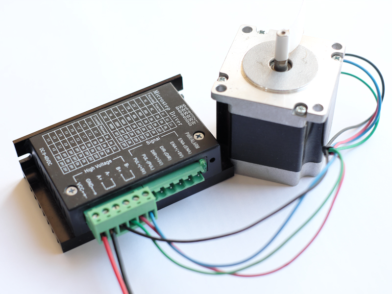
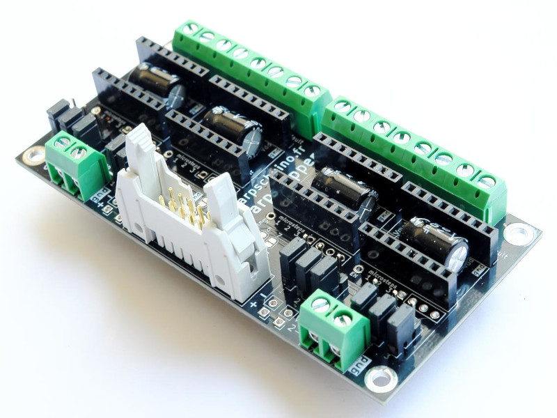
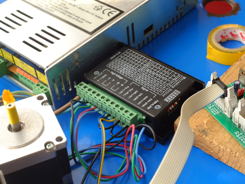
First, a new board,
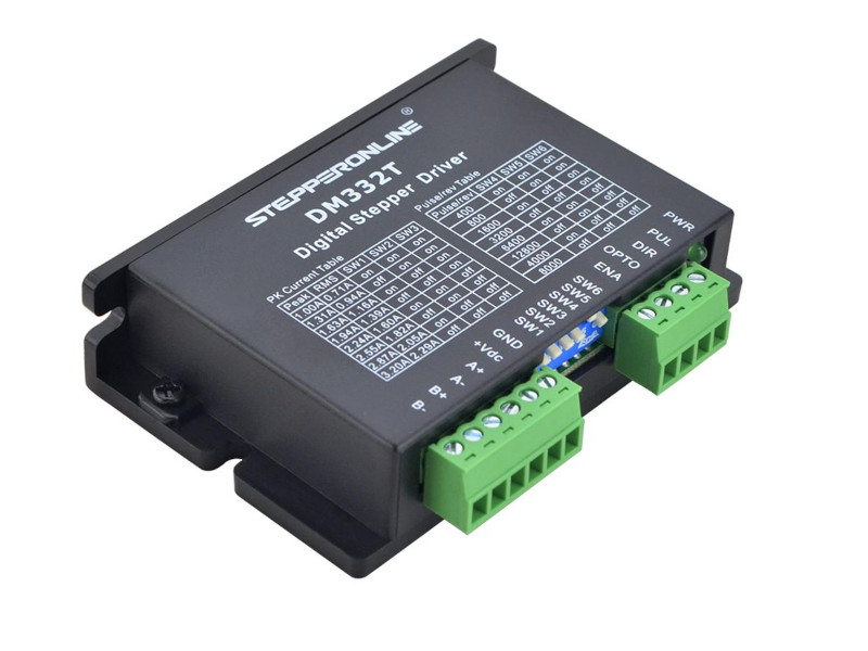
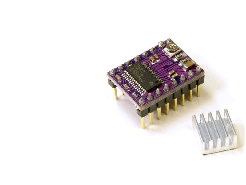
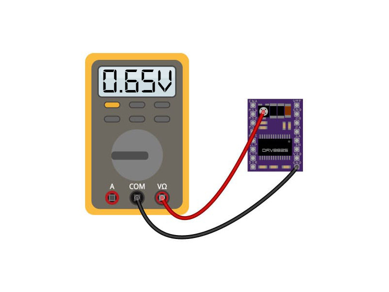
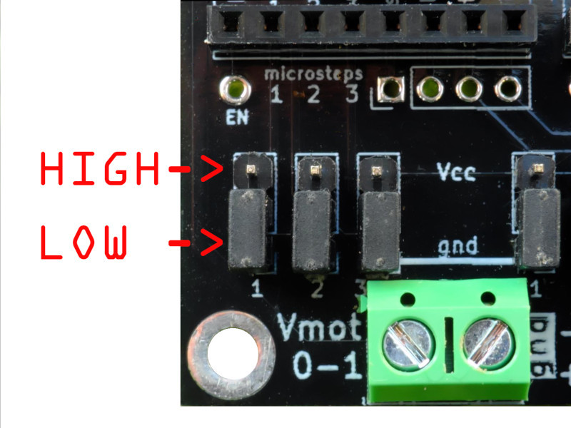
the arpstepper which allows stepping motors to be controlled in DMX with small drivers such as A4988, DRV8825, TMC2208 or compatible.
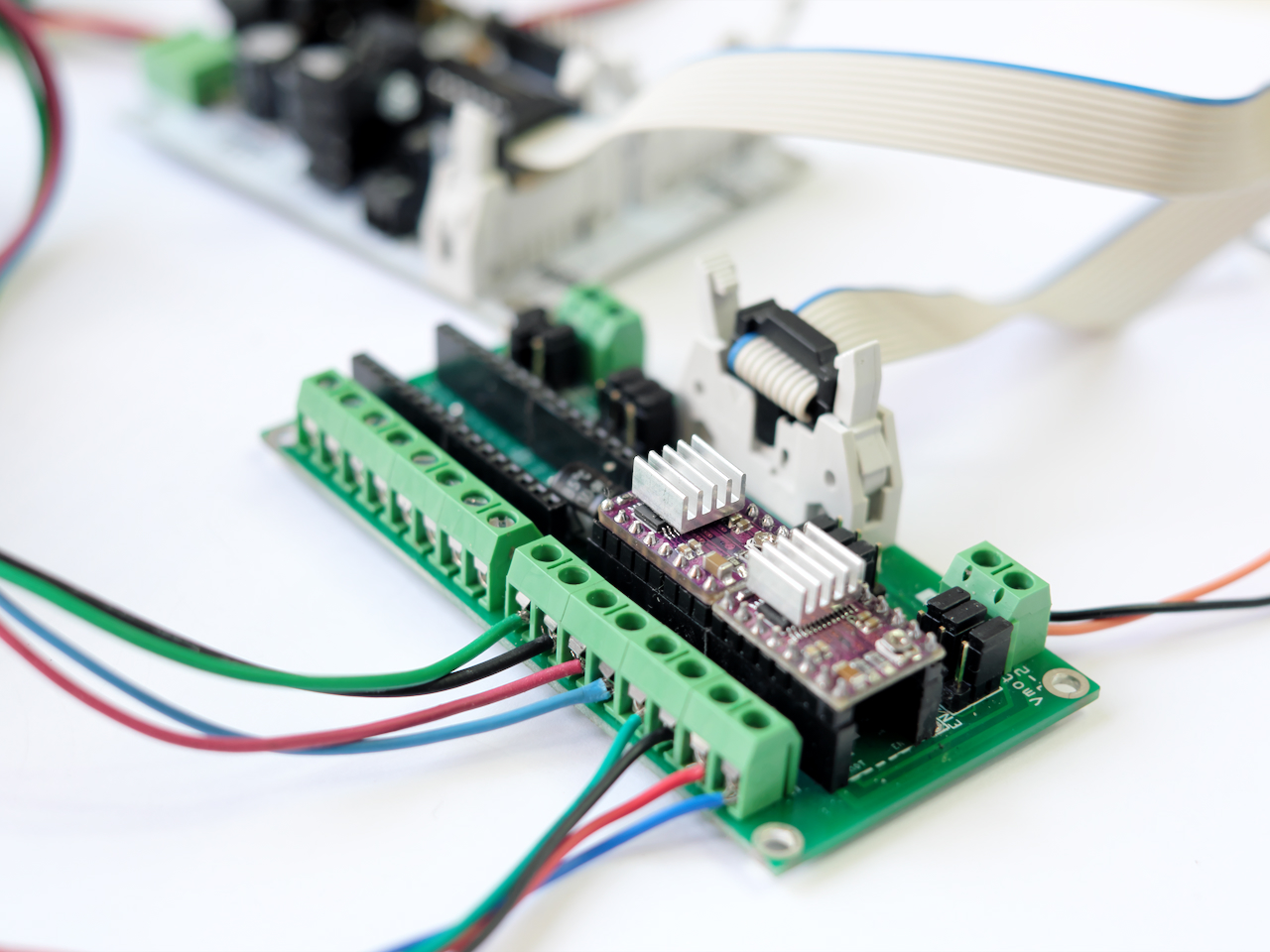
But that's not all, we have been developing a dedicated library for over a year now: the ArpStepper
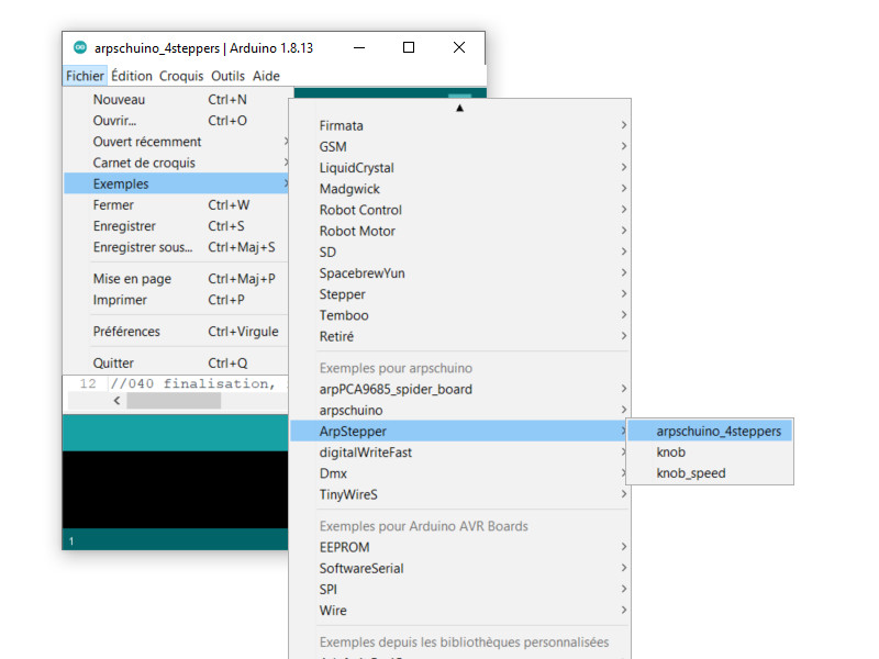
To install it you just have to update the arpschuino core (version 1.1.0).
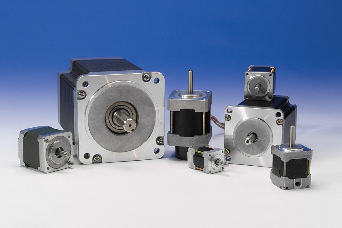
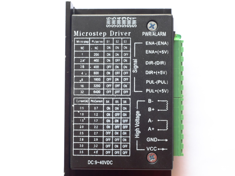
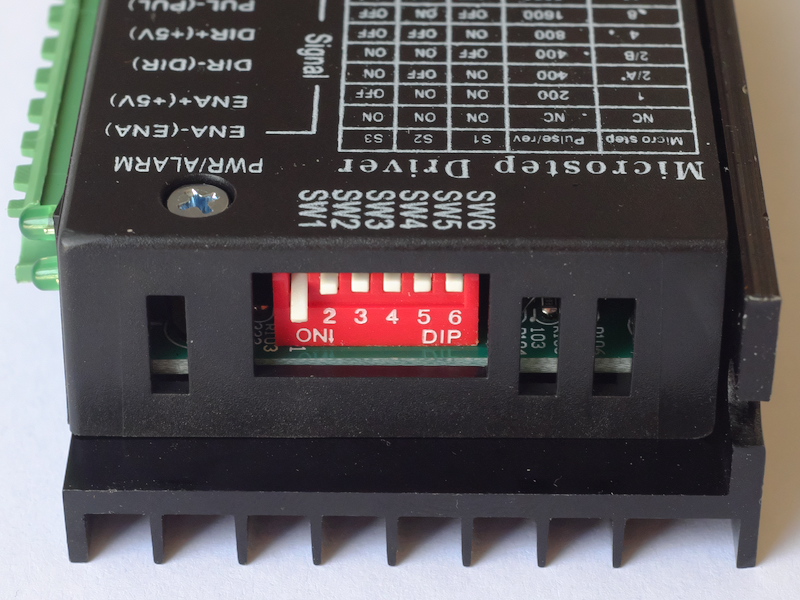
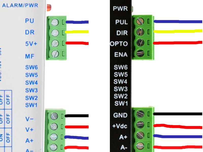
And finally, our stepper motor tutorial has been completely revised,
you will find everything you need to control one or more motors in DMX,
from bigger to smaller, with different types of drivers.
March 21 2021
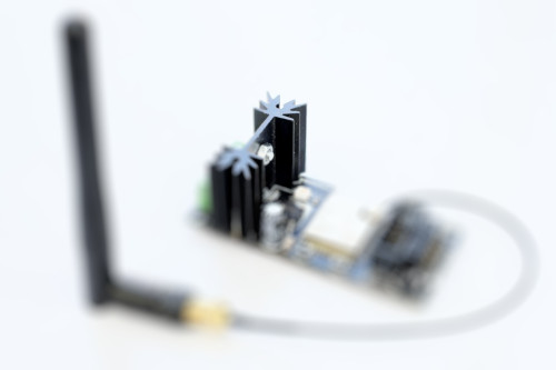
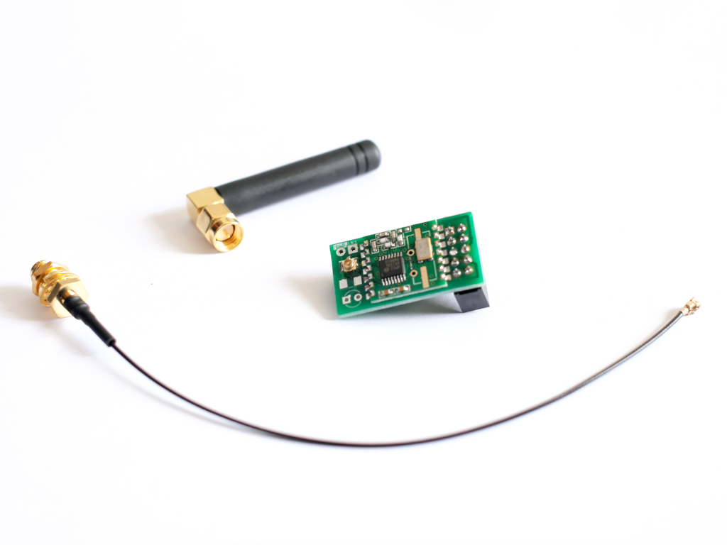
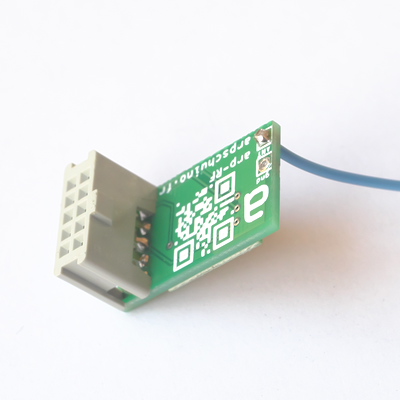
And here are external antennas for the wilulus, arpsensorsRF and arpRF.
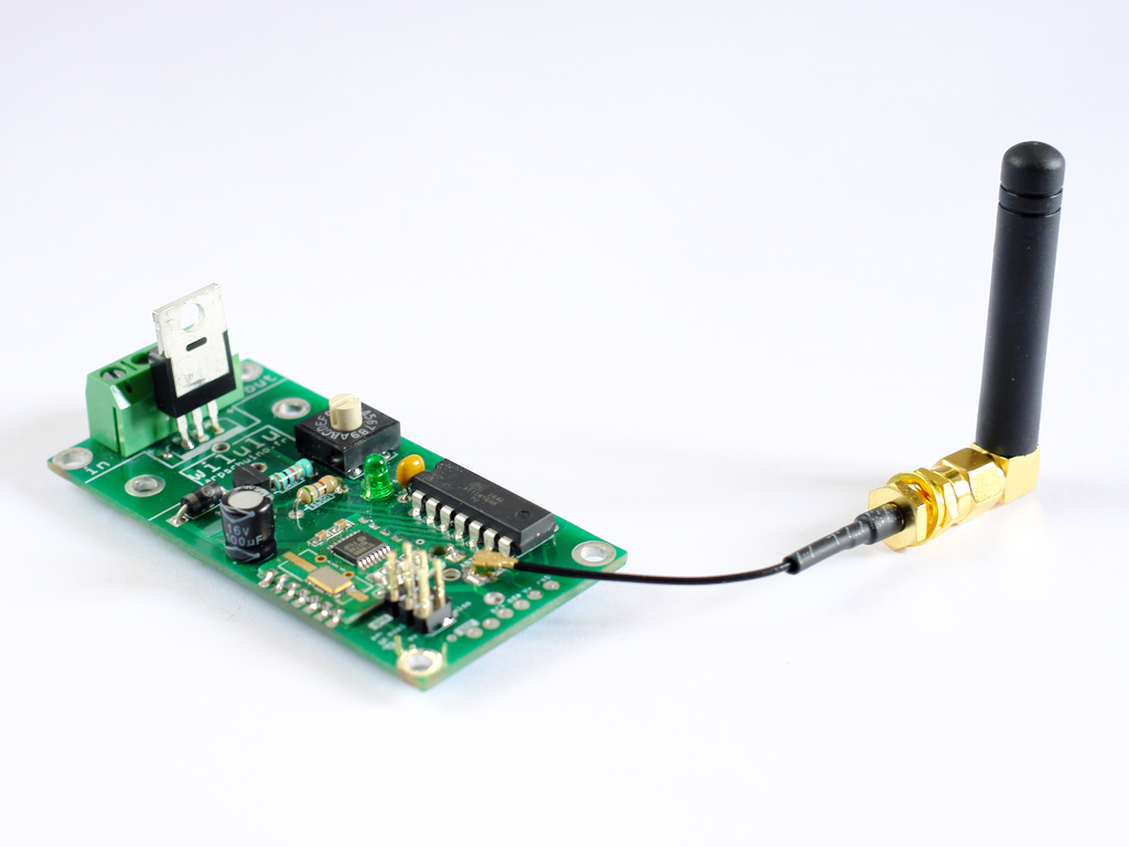
Necessary as part of a metal enclosure, an external antenna also slightly improves the RF range.
An IPEX socket and an IPEX> SMA cable allow these antennas to be fitted to our cards.
For arpRFs, choose the new arpRFr3 with IPEX footprint:
february 27, 2021
6 years already ...
Welcome to our two new members, and thank you to all the users who follow us.
January 3, 2021
We wish you a Happy New Year 2021.
December 02 2020
For this end of the (troubled) year, we are offering you a white arpschuino².
It is a very small series of 10 copies, the specifications are strictly identical to the classic, green models in version 6.2.
We wish you a merry festive season.
october 02 2020
If you visit the Nuit Blanche
this saturday at st Eustache church in Paris,
do not miss the Guillaume Cousin installation (arpschuino inside ;)
September 11,2020
Just a note to wish you a good season !
And to wish us all a 20/21 season less disturbed than the previous one ...
Jully 17,2020
Holidays !
Arpschuino is taking vacation until August 17th.
Orders are still taken care of until Wednesday 22.
Happy Holidays to all.
Mai 25,2020
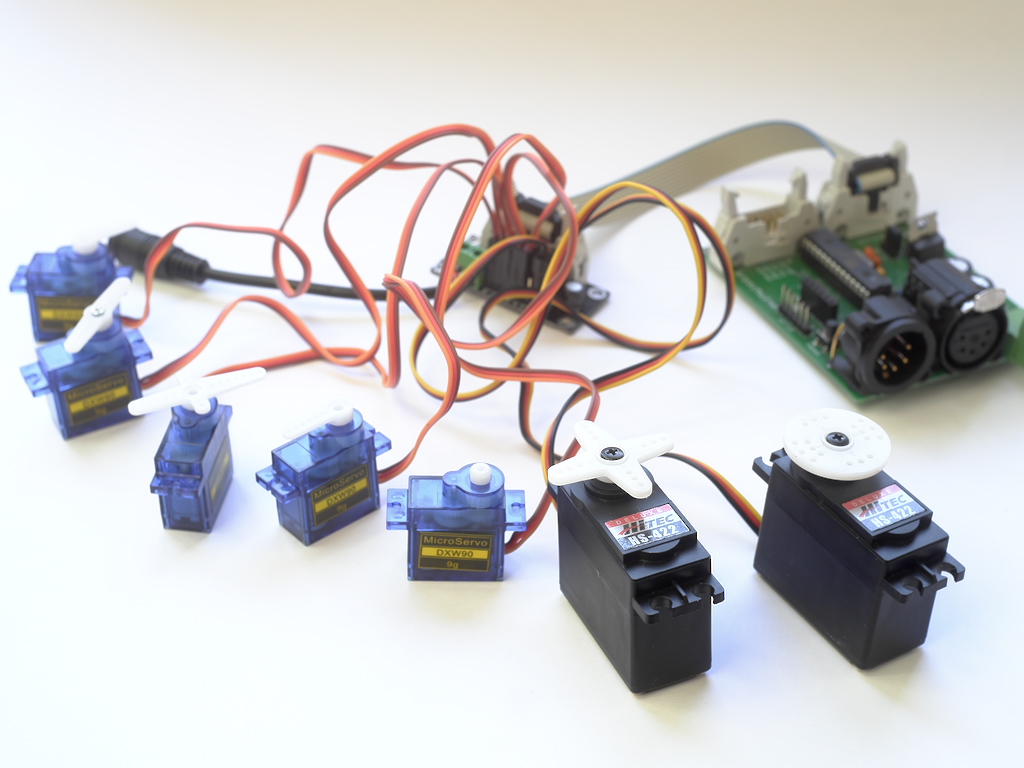
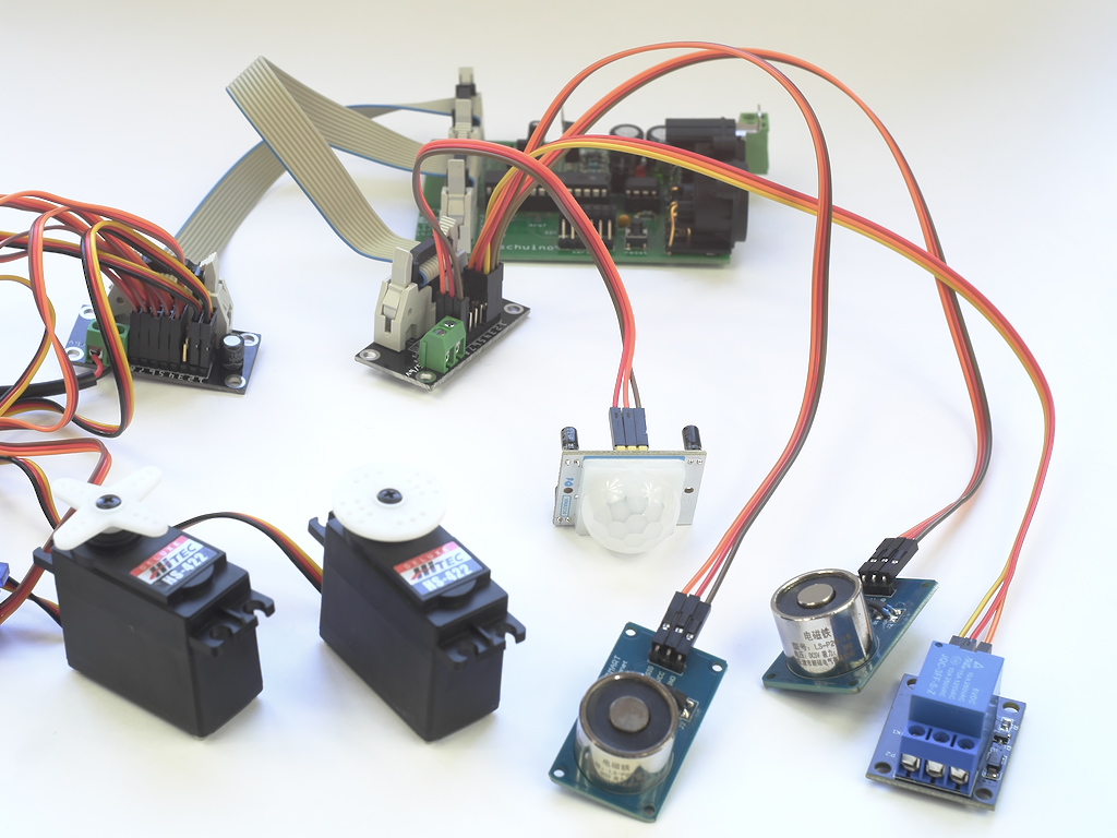
In the wake of the arp>servo, here is the servo tutorial.
You will find there all the necessary informations to control up to 16 servomotors, in DMX, with the arpschuino.
On this occasion, the arpschuino core has been updated, with the addition of the arpschuino_sevo code.
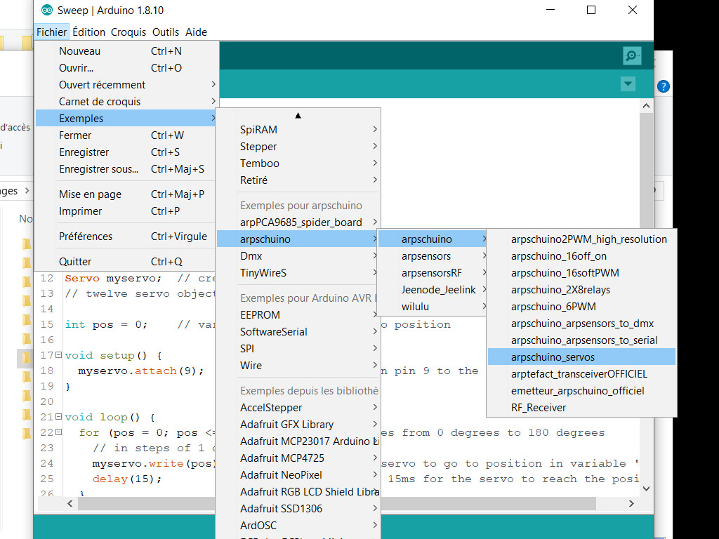
If anything seems unclear or imprecise, please let us know (arpschuino@gmx.fr)..
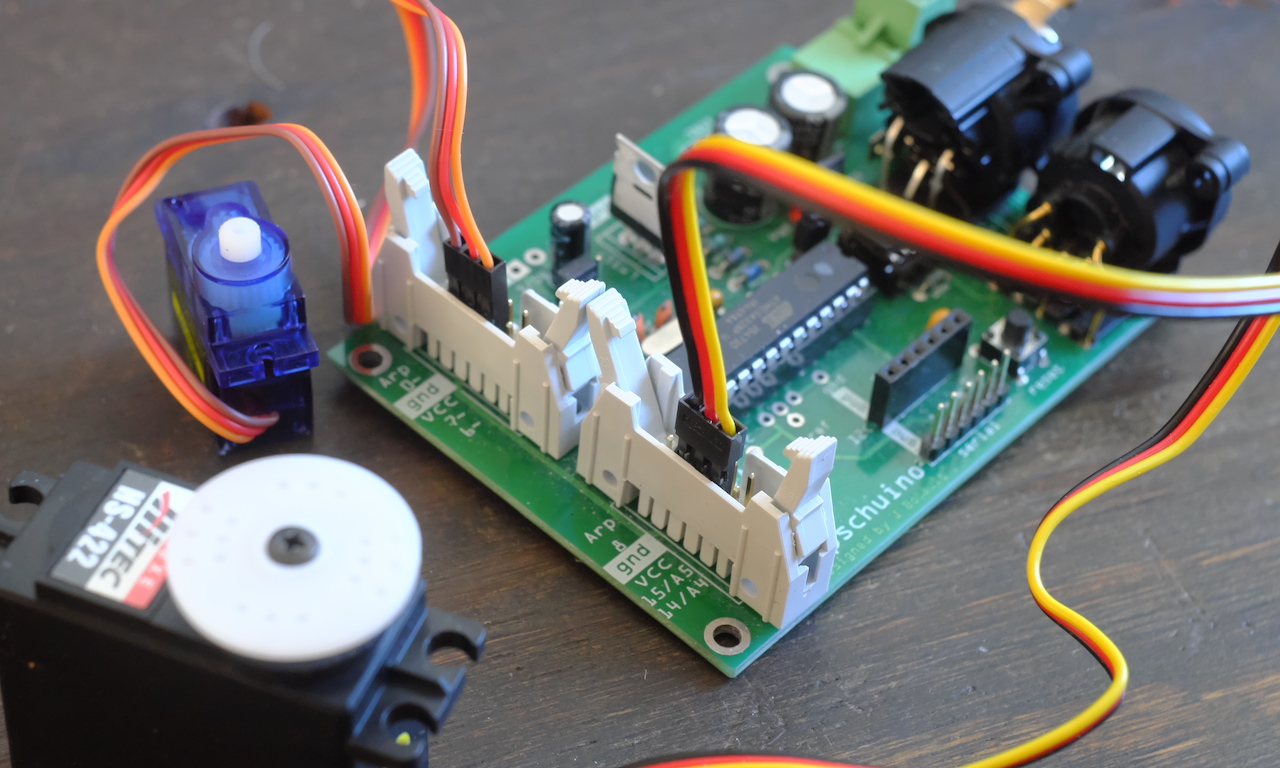
Mai 22,2020
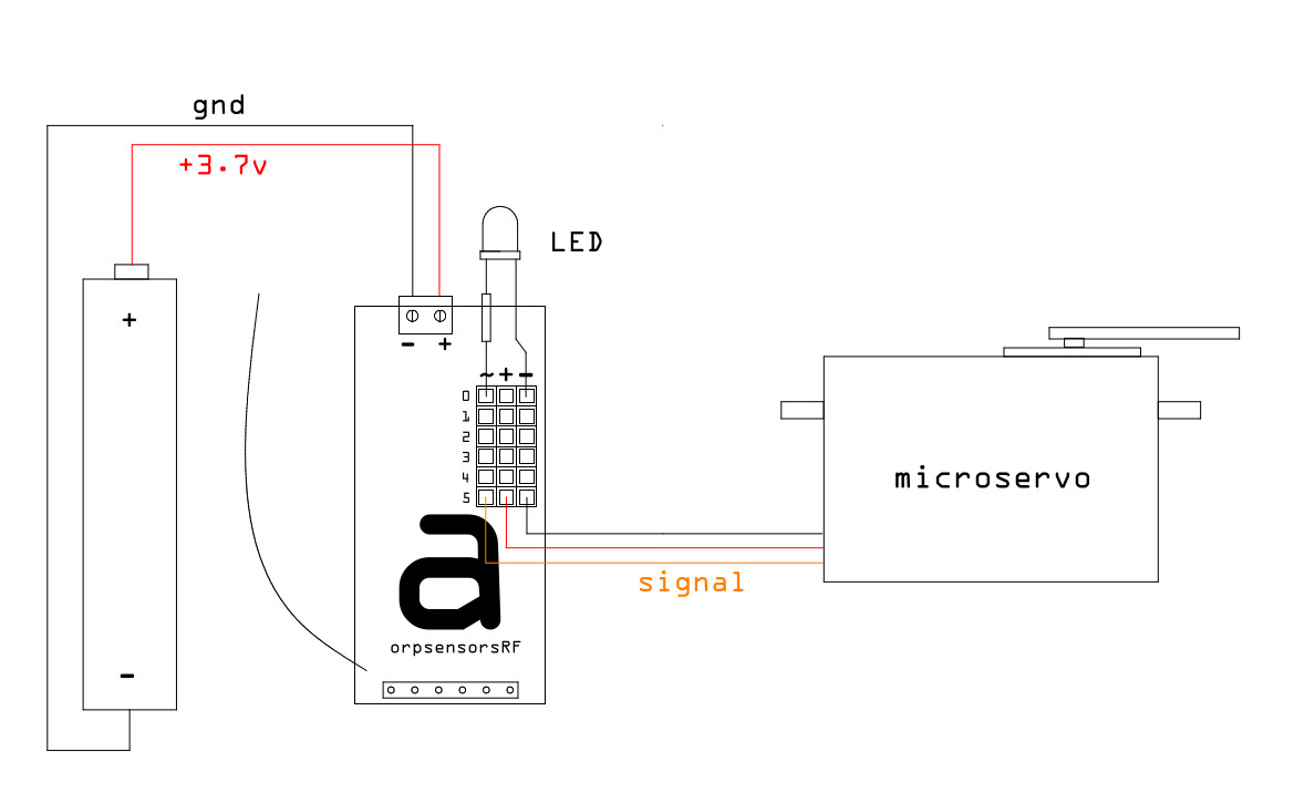
Here is the small board of May, the arp>servo :
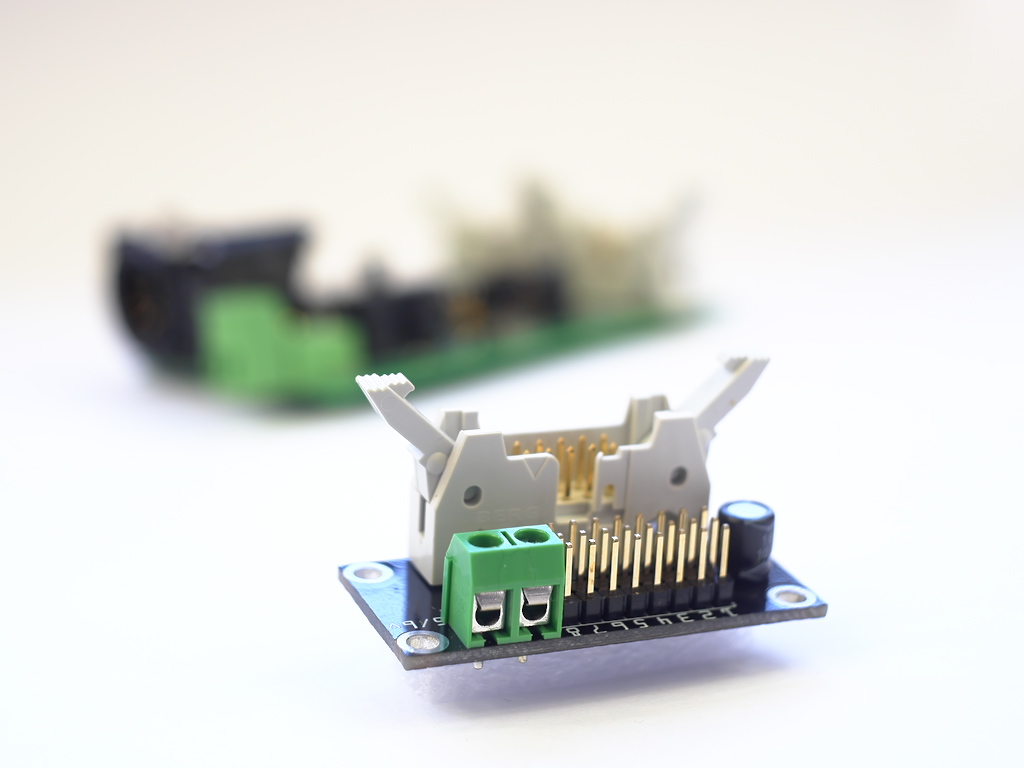
Thanks to it you will be able to connect up to 16 servo motors on an arpschuino.
And that's not all, the 3-pin male connectors (gnd, Vcc, signal) also allow you to connect many sensors and actuators.
To be continued: a servo motor tutorial is in preparation.
April 29, 2020
We might as well take advantage of this period of lockdown...
We are writing a library for controlling the stepper motor, speed and position.
So that everyone can have fun with it, it is offered for testing on the arduino forum(french section), do not hesitate to go take a look.
April 19, 2020
Our call for rodoids was well relayed, especially by the city of Montreuil, and worked well.
Thank you to all the contributors, we are still looking for it as production continues, in close collaboration with the fablab La Verrière at Montreuil.
Despite the lockdown, the series of small boards continues, here is the arp> terminal² :
It is an arp>terminals with in addition an access to ground (gnd) and to 3.3 / 5V (Vcc).
The "classic" arp>terminals remain available.
March 29, 2020
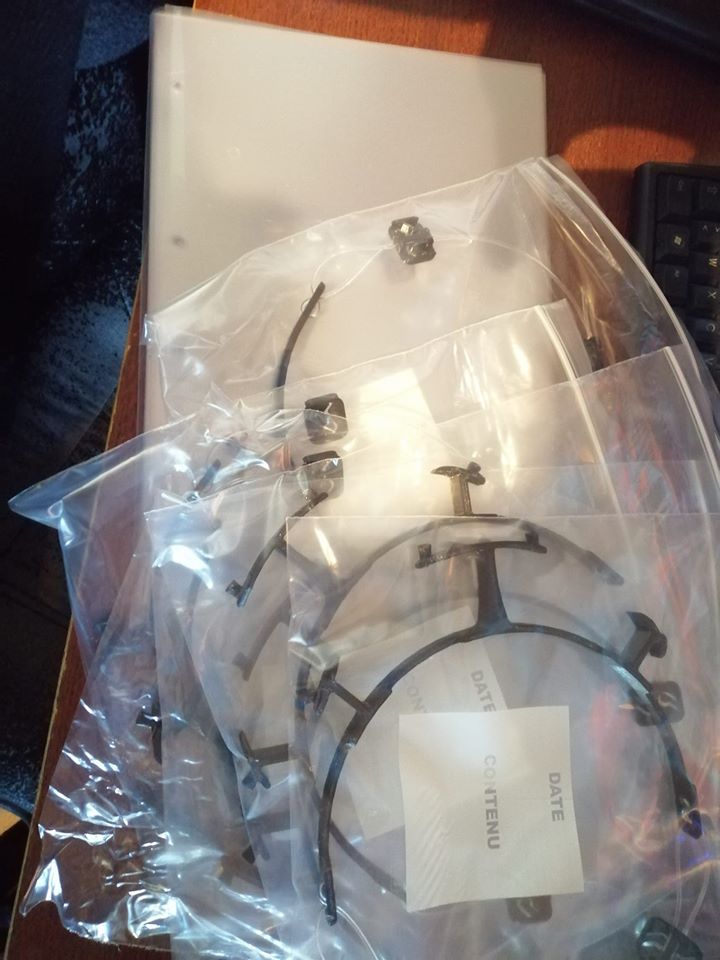
Currently, the 3D printer arpschuino running at full capacity to produce visors for caregivers of Montreuil Hospital.
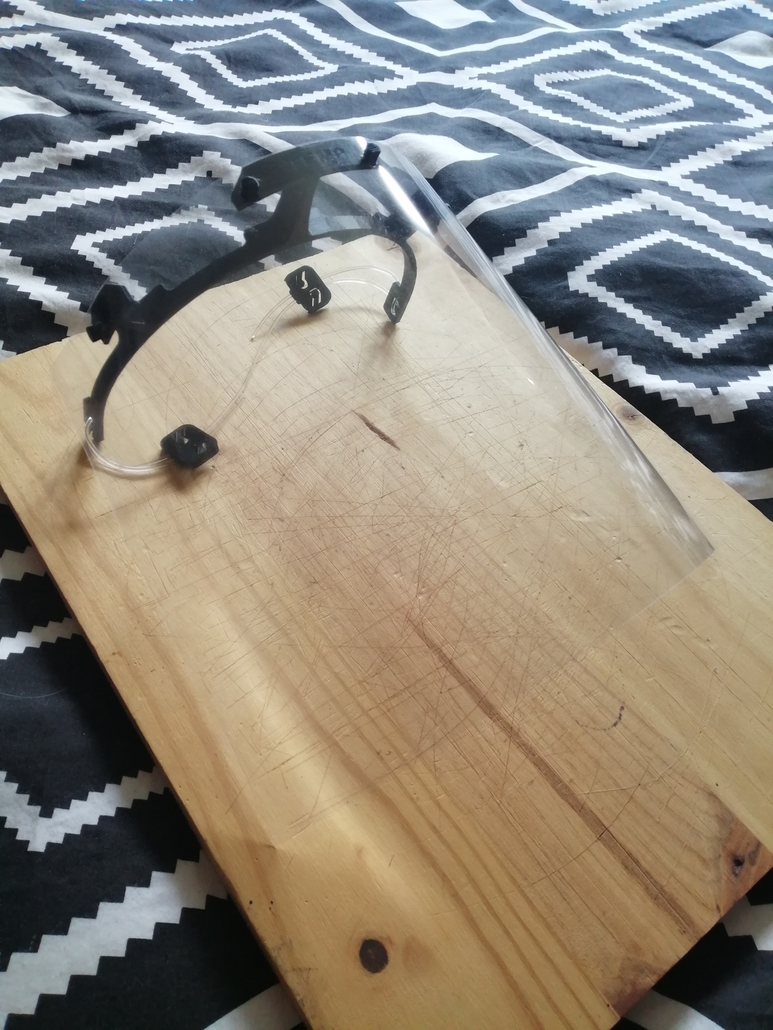
The peak of the epidemic is coming to the Paris region.
March 19, 2020
Locked at home we take the opportunity to tidy up !
All our STL files for 3D printing are now on our github in the "designs" repository.
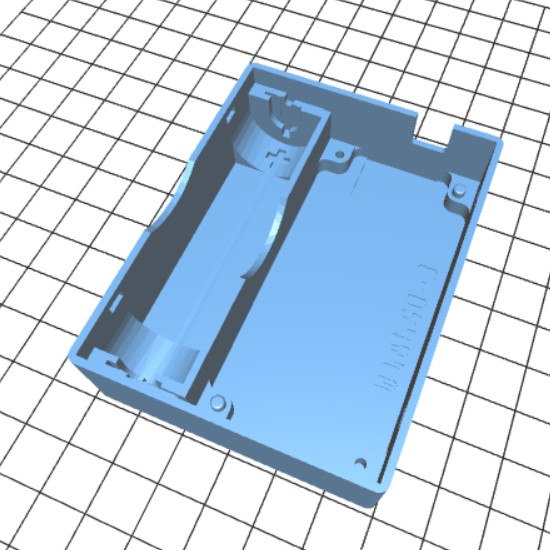
There you will find boxes for our boards and more.
March 18, 2020
In these difficult times of general lockdown in France, arpschuino continues its activities.
Here is a new little board for this month, the led board :
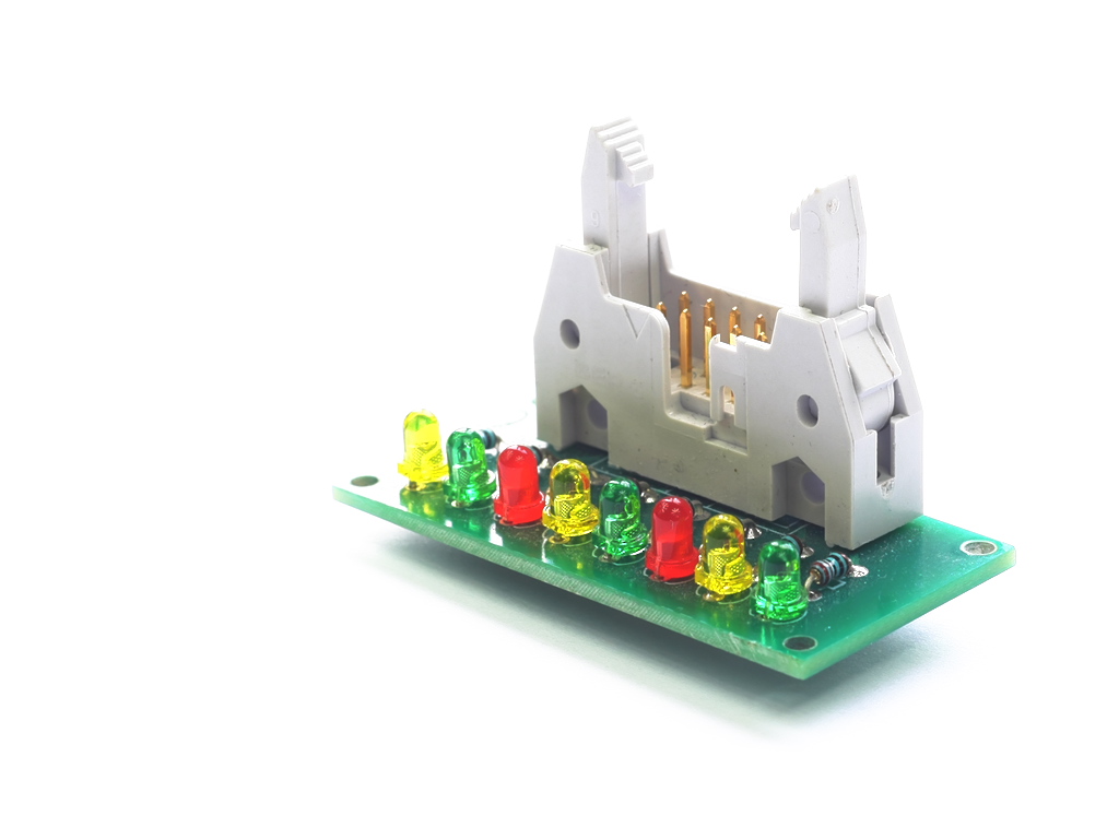
A simple board with 8 signal LEDs, it can be used to debug or to make a bargraph.
We were asked if shipments continued during the lockdown, the answer is yes, as long as possible,
for small consignments which do not require registration by post, i.e. packages less than 3 cm thick.
We take the usual precautions to avoid contamination, hand washing before touching the kits ect.
Be brave !
February 29, 2020
5 years !
This February 27, arpschuino.fr turned 5 !

Thank you to all of you who trust us.
February 8, 2020
Continuation of the series of small boards!
With this time something more substantial, the arpower mini.
It is quite simply a single-channel arpower, modeled on the power part of the wilulu.
It is ideal for using two high resolution (12 bit) PWM outputs of the arpschuino².
A suivre...
January 28, 2020
Over time, we have made a number of small utility boards, depending on our needs.
Generally we did not take the time to publish them on this website...
So here's our resolution for the new year : to put online one a month until at least June
We will try to stick to it !
So here is the first: the board voltage regulation.
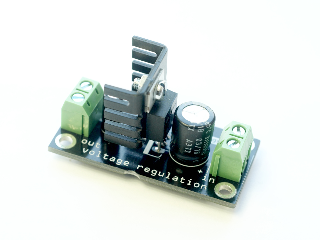
We start gently, it is a simple voltage regulator but this can be very useful on certain assemblies.
To be continued : a new little board in February.
January 1, 2020
Happy 2020 to all, in 3D !
september 24 2019
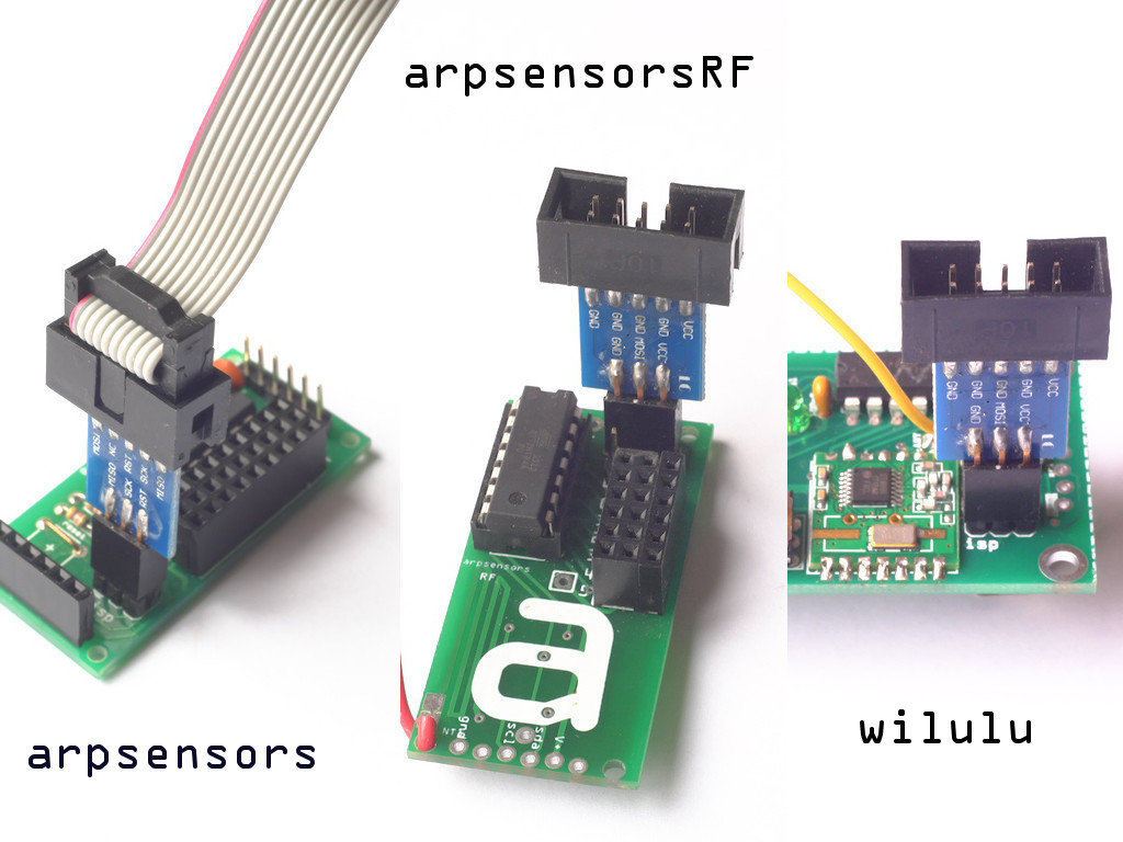
Here is a new version of the arpsensorsRF:
The arpsensorsRFregulator.
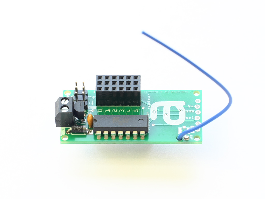
As the name suggests, it is equipped with a regulation system, which allows to supply it with a voltage between 3.5 and 12v.
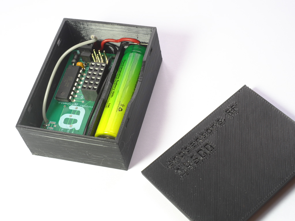
The opportunity to build an enclosure with a 14500 li-ion storage slot:
The arpsensorsRF in the classic version remains available for assemblies with a power supply between 2.8V and 3.6V.
august 30 2019
It's the end of the holidays!
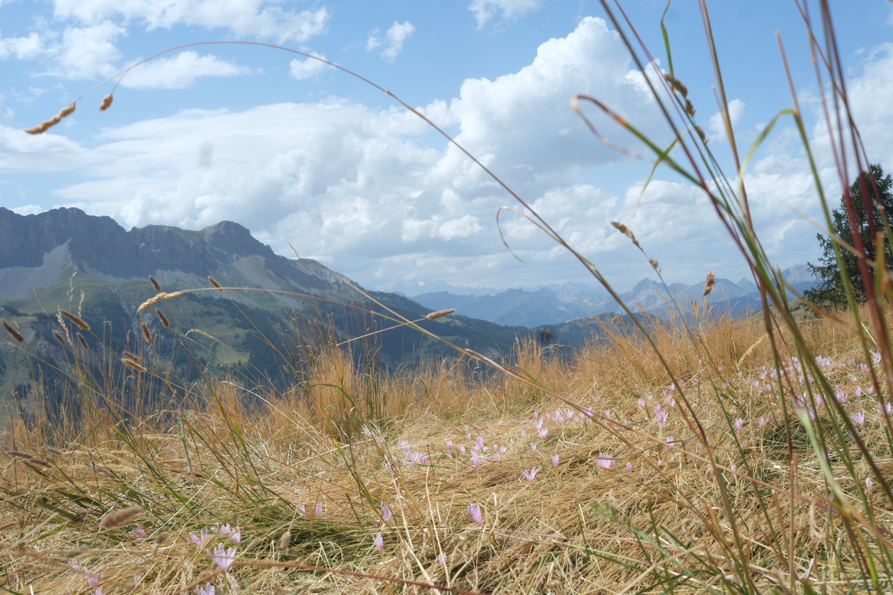
Adieu alpine pastures or sunny beach, the arpschuino resumes its activities...
jully 13 2019
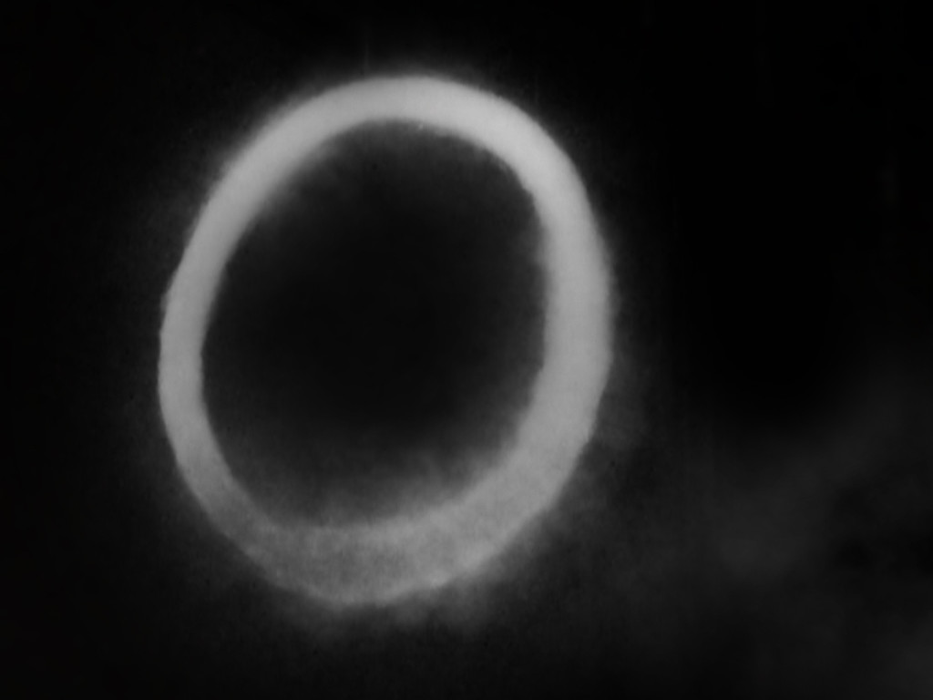
For this end of season, we would like to highlight the work, in different areas, two arpschuino users.
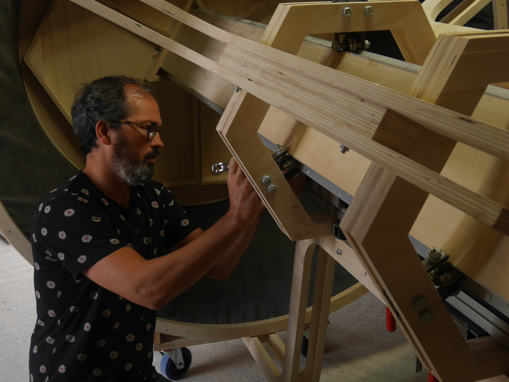
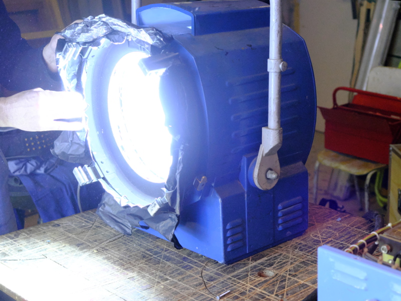
Guillaume Cousin and his giant smoke rings of le silence des particules,
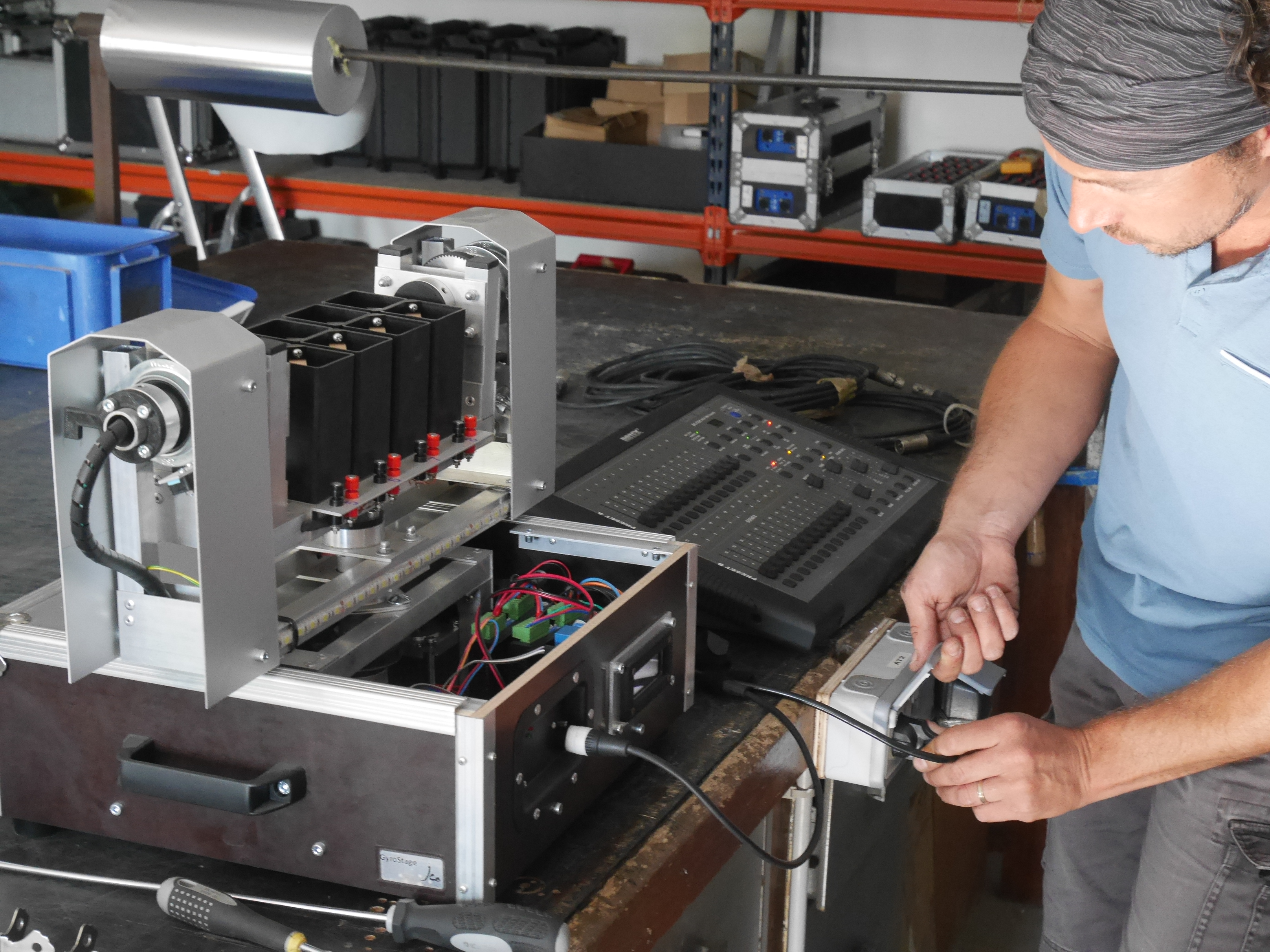
and Nicolas Moinet and his incredible Gyrostage, a lyre for fireworks.
Congratulations gentlemen !
ATTENTION: the site will be closed during the month of August.
june 16 2019
We do not give much news, but that does not mean that we do nothing !
A lot of projects in progress but we found the time to get a brand new 3D printer.
A Prusa i3 MK3 S originale. It's just assembled and has not even uttered her first cry !
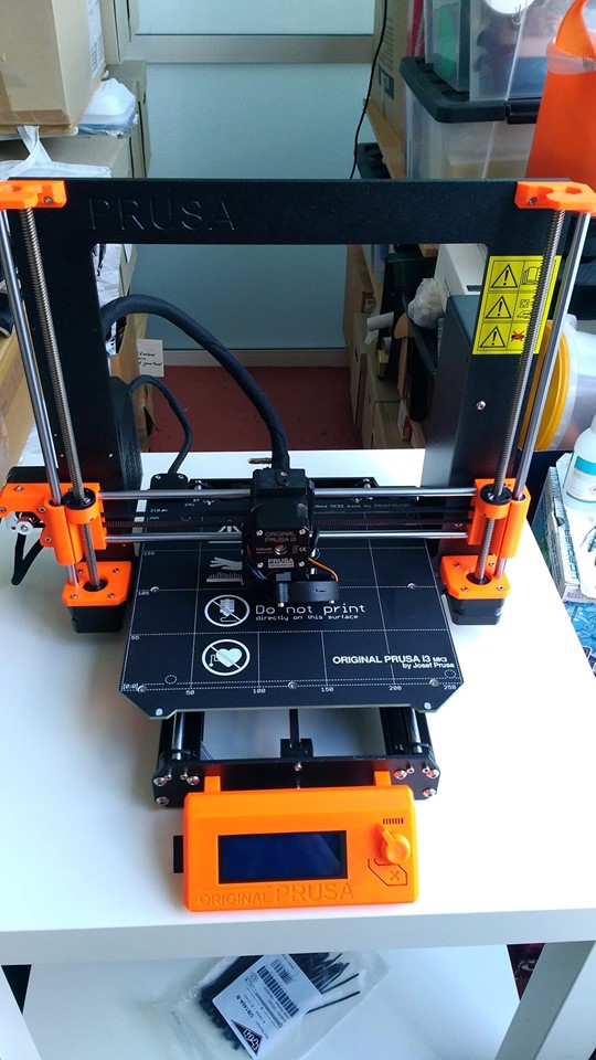
More on our facebook page !
february 22 2019
Here is a new tutorial !
It's a big tutorial about the wilulu, we tried to be as complete as possible and to put some examples.
As always, do not hesitate to tell us if you find errors or things that do not seem clear to you (arpschuino@gmx.fr).
And again an update of the arpschuino core, this is a debug of some examples, the details are available on this page
Finally, we do not resist the desire to present our new workshop :
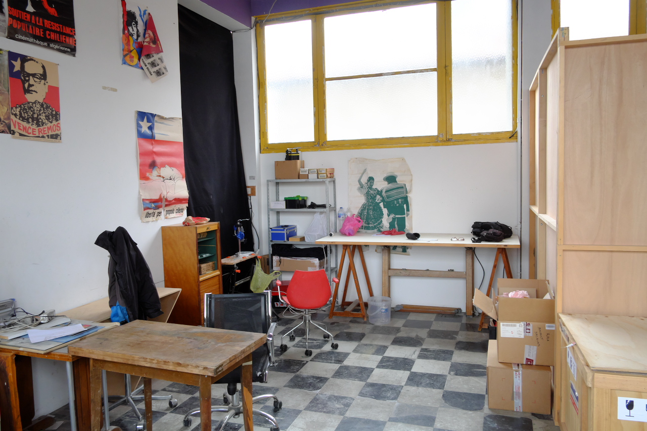
And thank you to all the "Moccards team" who welcomes us.
January 25, 2019
A new update to the arpschuino core !
See the previous post to apply this update from the Arduino software.
This is a fix, some examples no longer compile because of a syntax error (calcul_freq instead of rf12_calcul_freq).
We still took the opportunity to make an improvement in the examples and the default code of wilulu:
In order to preserve the li-ion batteries, the wilulu goes to sleep mode if the supply voltage drops below 2.8v.
This should prevent you from damaging accumulators by forgetting to remove them after a performance.
The information on this update is available on this page..
January 15 2019
The library and the arpschuino core have been updated.
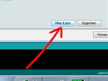
To apply this update from the Arduino software, click on Tools / Board / Board Manager then,
if the core is already installed, find it in the list and just click on Update .
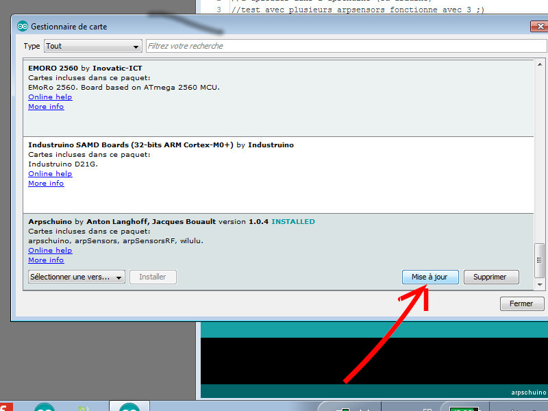
In program, new features and possibility to change the transmission/reception frequency of radio boards equipped with an RF12.
The examples have been reviewed in this sense.
New example codes also with the source code of the arptefact::transceiver
and aprschuino2PWM_high_resolution which allows to benefit from the fine gradation (12 bit) directly on 2 outputs of the arpschuino.
All the information on this update is available on this page..
A wilulu tutorial is in preparation, the method for changing the radio frequency will be explained in detail.
Do not hesitate to contact us if you have any questions: arpschuino@gmx.fr.
January 1, 2019
Happy New Year.
Thank you to everyone who trusted us in 2018.
november 30, 2018
It's ready !
In addition to our different boards, we have decided to offer you some devices boxed, ready to use :
the artefacts.
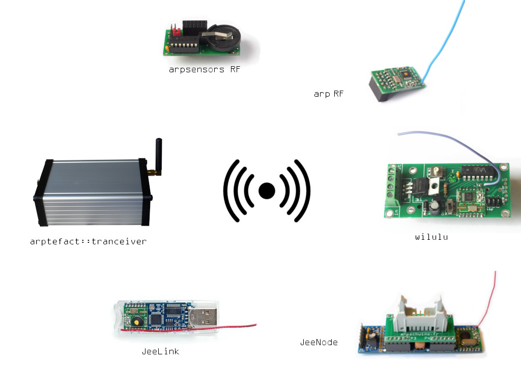
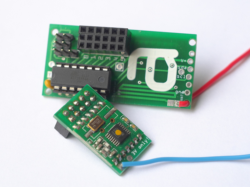
Here is the first of the series, the artefact::transceiver.
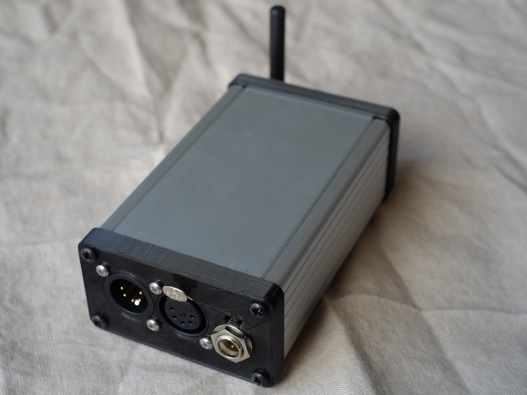
It is a transceiver to use with our wilulus , arpsensorsRF or with a second artefact::transceiver.
We are already looking at the design of other members of the artefact family.
If you have any ideas, suggestions, let us know: arpschuino@gmx.fr.
October 5 2018
You are many for this early season to trust arpschuino. Thank you !
Our last arpschuino²R5 are gone like hotcakes, we have to deal with the out of stock but here is the arpschuino²R6 :
Only one new, but size: you can now optionally mount a pre-regulator that allow to supplies the board with a voltage of up to 24V.
We are a little late with our transceiver but do not worry, it come !
June 29, 2018
You may have seen it already on our facebook page,
we are manufacturing transceivers based on arpschuino² and arpRF .
We are refining and testing them a little this summer and they will be ready in september.
We are thinking more and more about organizing short courses/initiations. Things are moving forward and should materialize next season. If you are interested do not hesitate to contact us:
arpschuino@gmx.fr.
April 13 2018
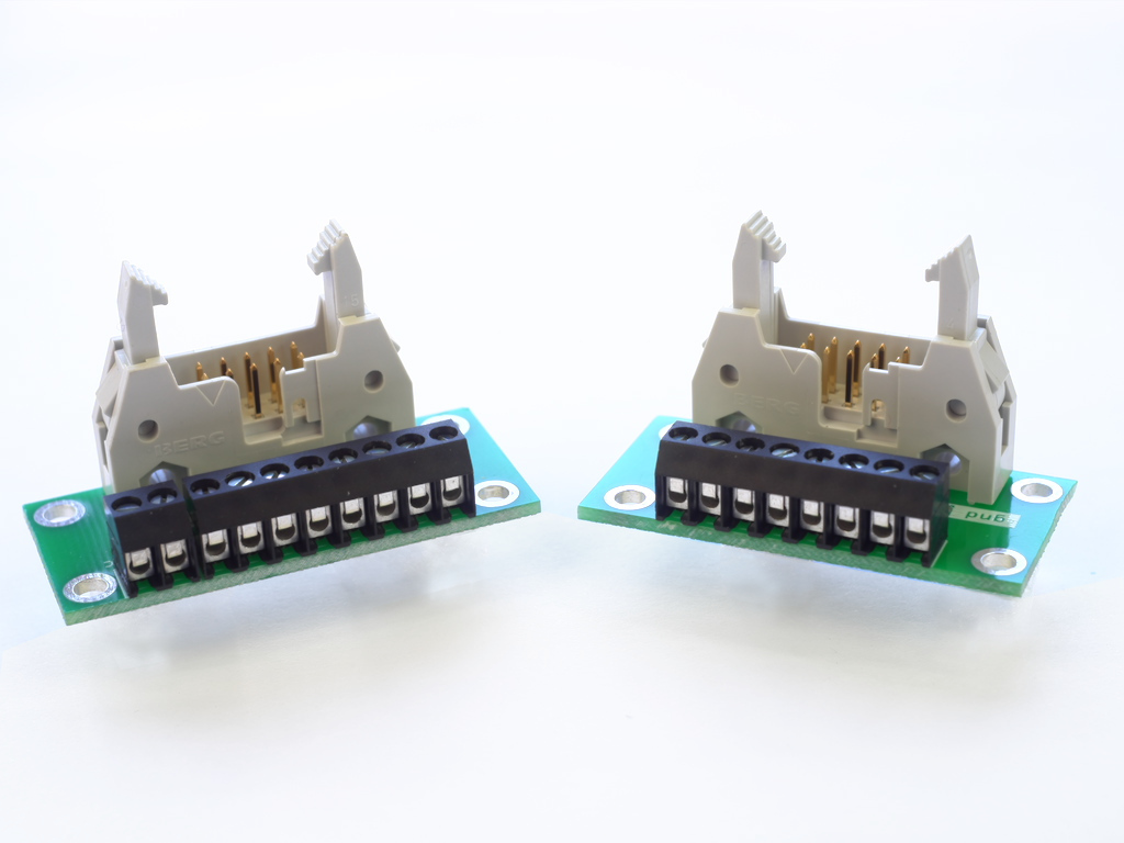
Two news little things for this month the arp>terminals
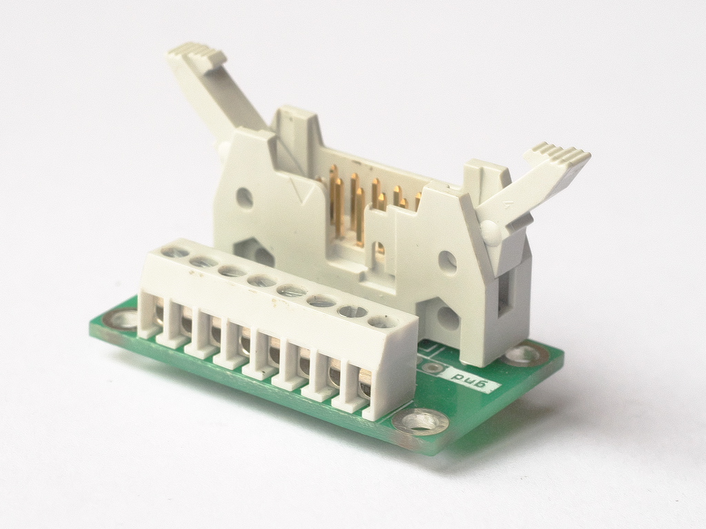
an adapter to terminal blocks for arpschuino, and arpschuino² that goes to revision 5 (R5):
With a new marking of the I/O, compatible with the core arpschuino ,
the zener diode deleted and the addition of a capacitor on the reset line of the serial port.
March 8 2018
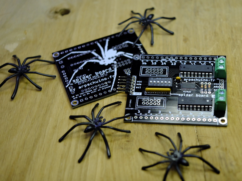
Here is the spider board !
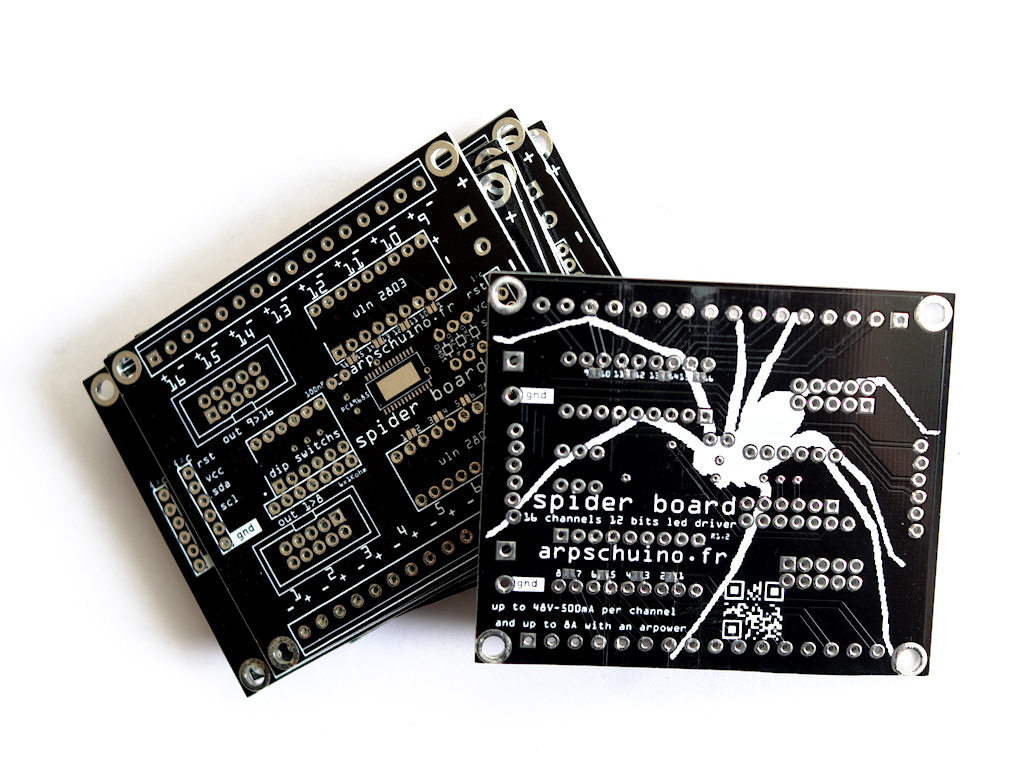
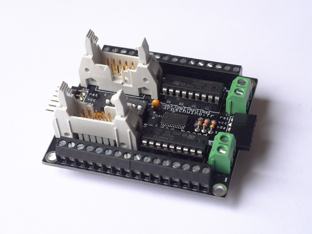
It is pluggable on the I²c port of the arpschuino, and allows a 12-bit ultra fine dimming for LED, on 16 circuits.
For LED, the result is much more satisfying than with 8-bit dimming.
The arpschuino core has been updated with the addition of the "arpPCA9685" library for the spider board;
with also a source code for saving power in the examples of the wilulu.
For more information, do not hesitate to contact us: arpschuino@gmx.fr .
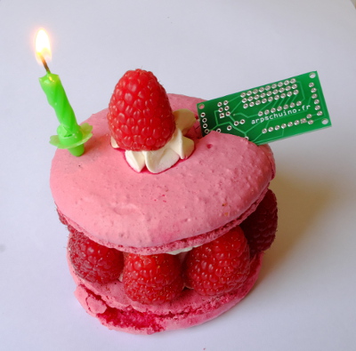
February 27, 2018
arpschuino.fr is 3 years old!
A bigger cake this year because the team has grown, we are now 6.
Thanks to you, arpschuino is also a community of users more and more important, thank you all for your confidence.
February 4 2018
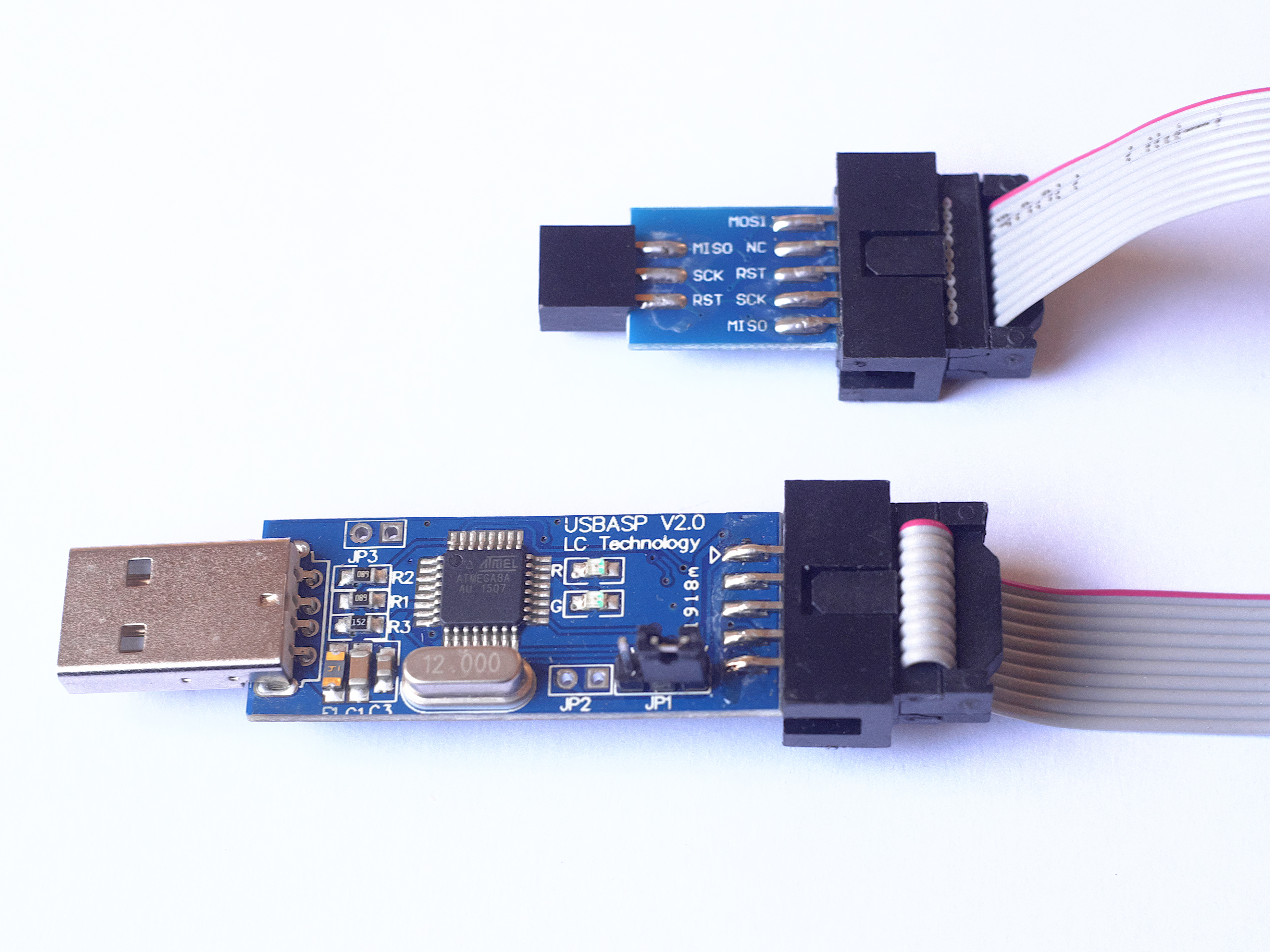
After our tutorial program an arpschuino, here is the continuation : program an arpsensor or a wilulu.
Comme l'arpschuino, toutes ces cartes sont reconnues dans le core arpschuino et bénéficient d'une programmation simplifiée.
Nous vous proposons aussi maintenant un programmateur ISP, parfaitement adapté à nos cartes : l'USBasp.
December 30 2017
Looking back on this year 2017.
In France, you are more and more users to trust us, thank you all, it encourages us enormously! Internationals users are also welcome!
We are now 5 in the team, everyone finds his place and we become more and more effective.
On the hardware side, 3 RF boards came this year: the arpsensorsRF, the arpRF and the wilulu.
New boards are in preparation, the spider board and its ultra fine diming, will arrive in January.
We also had great collaborations this year: with the Cirque Inextremiste (Exit),
the Surnatural Orchestra (Esquif),
Groupe Laps (Spider Circus)
and DCA, Philippe Découflé's company, (nouvelles pièces courtes,
currently at Chaillot theater).
We wish you a happy new year.
december 12 2017
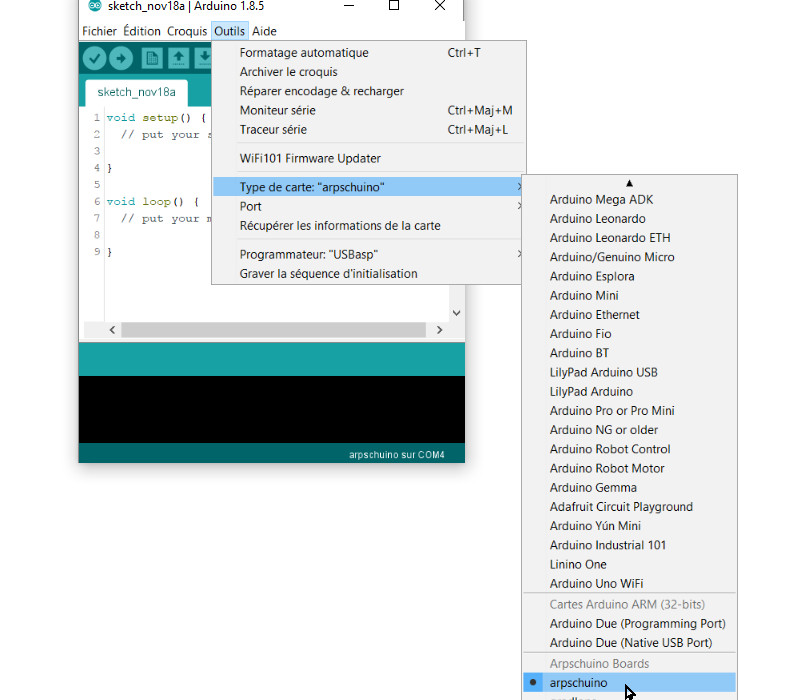
Reprogramming the arpschuino becomes much simpler with the creation of the "arpschuino core".
All our programmable boards are now recognized by the Arduino IDE, all libraries and source codes are automatically imported.
Thanks to Anton Langhoff for his work !
The arpschuino programming tutorial has been fully reviewed.
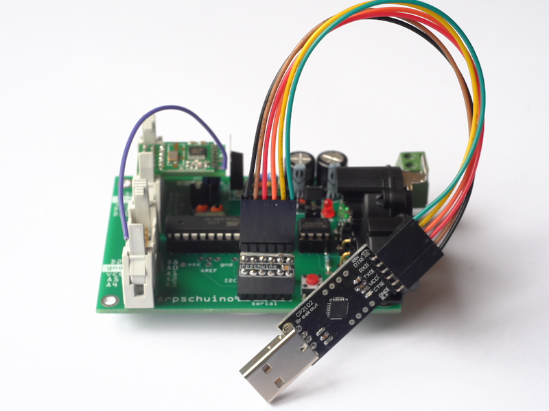
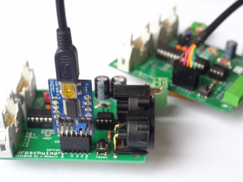
We now have a USB>serial programmer perfectly suited to arpschuino and cheap.
A programmer for the arpsensors , arpsensorsRF and wilulu will be available soon.
november 5 2017
The arpRF connector is now equipped with a keying.
The transmitter could be damaged as a result of bad connections, so we decided to fix it !
Continue anyway to put the arpschuino² jumper in 3V position before connecting the arpRF and unplug the arpRF before reprogramming if you use a programmer in 5V.
The tutorial on programming is being redone and will be online soon.
october 20 2017
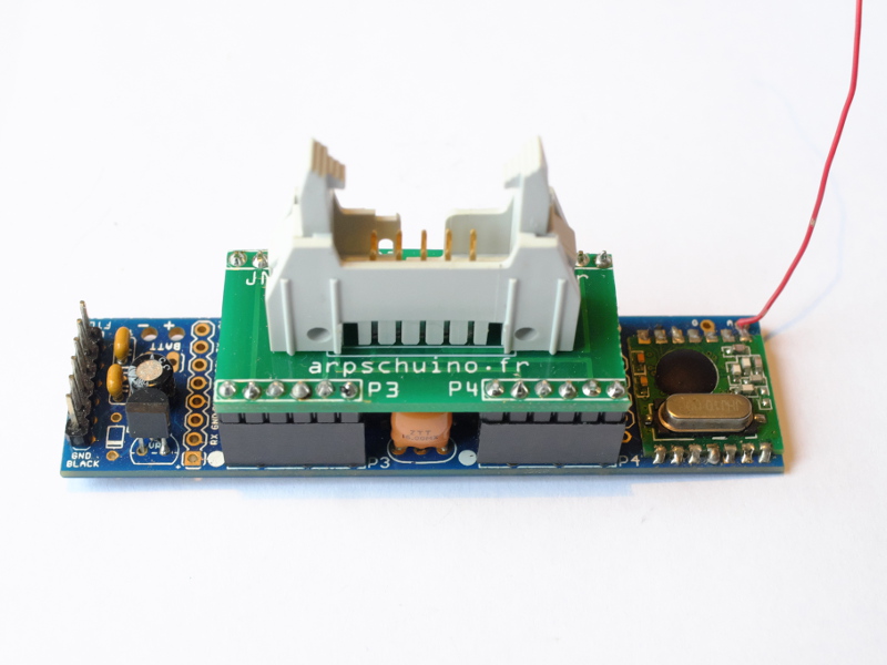
Announced for a long time, here is the wilulu
It is a small pocket dimmer, controlled by radio link from a computer or a light console and capable of dimming up to 8A.
Already used in show, they are used in Exit from Inextremiste circus
and Esquif from surnatural orchestra.
octobber 2 2017
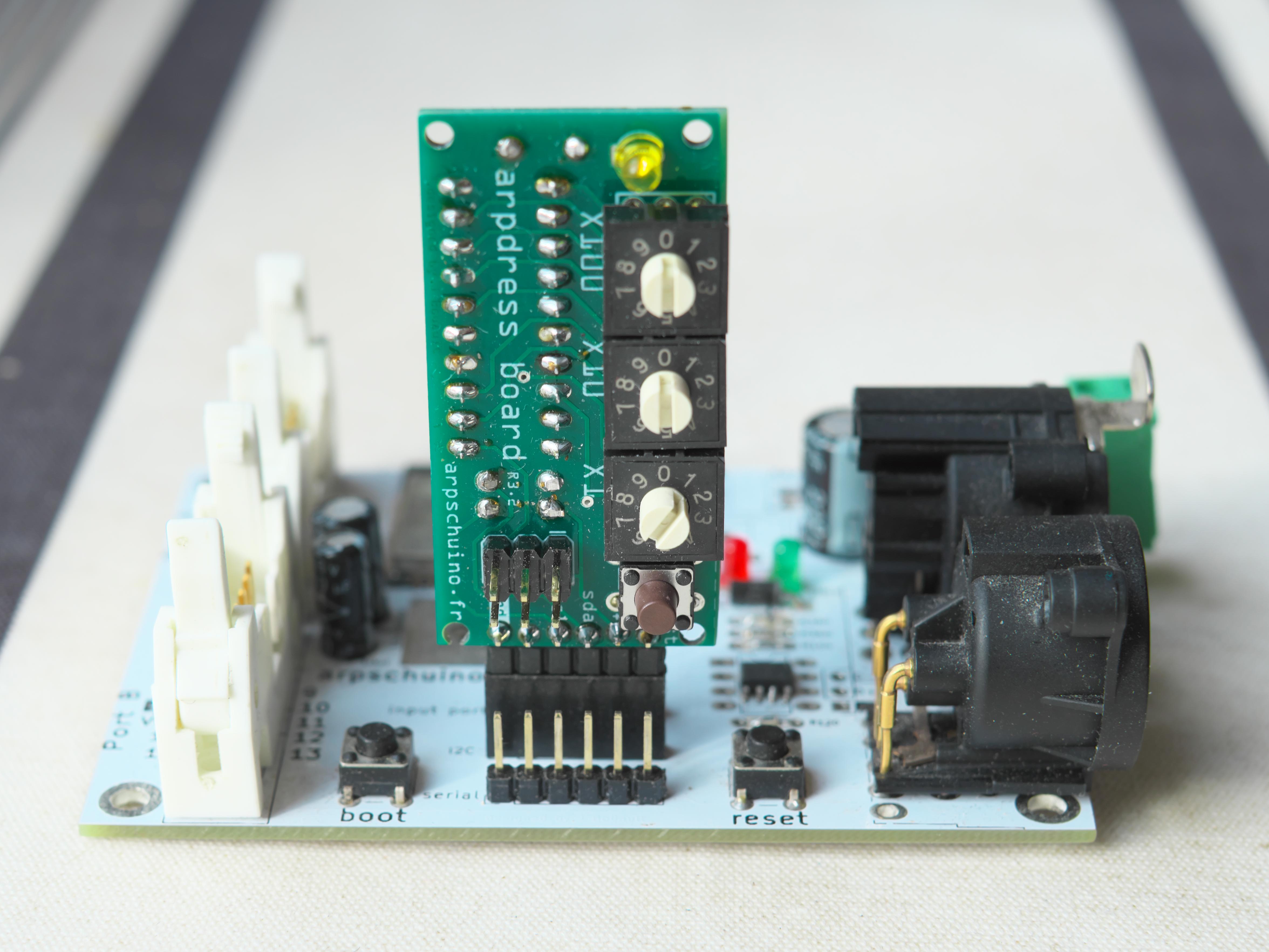
A new revision of the arpschuino², with the addition of a reset pin on the I2C port.
Concretely this will allow to reset the arpschuino² remotely from the arpdress board, notably in the case of a boxing.
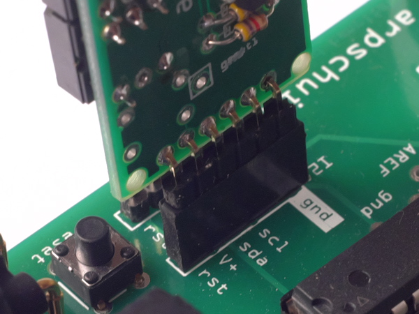
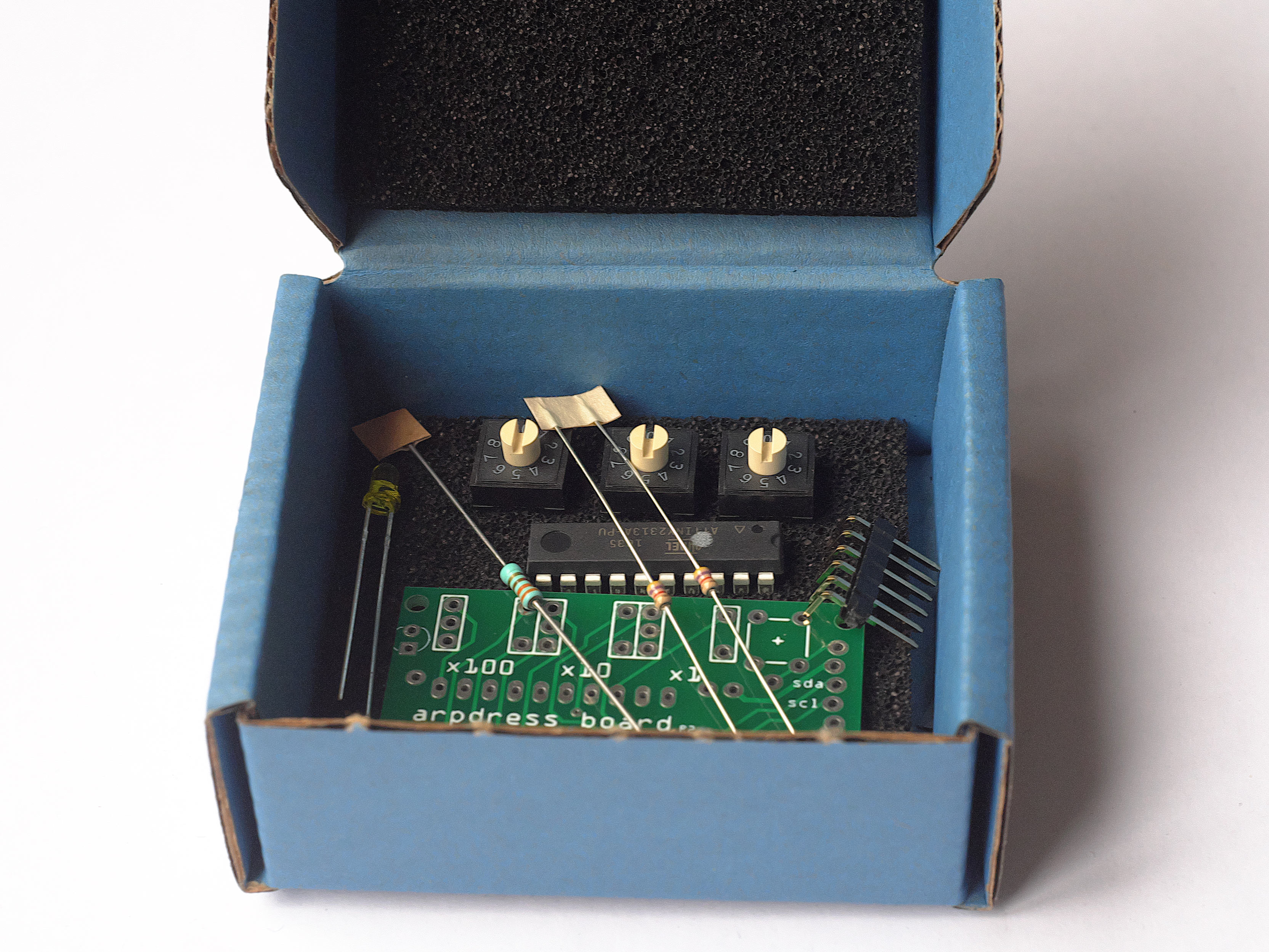
For arpdress board: new, more readable encoders.
The microcontroller is now directly soldered to the board and the arpdress board is now delivered in a small anti-static box
july 19 2017
Arpschuino.fr is currently on vacation.
You will be able to meet us this summer at the Aurillac festival with the Cirque Inextremiste team.
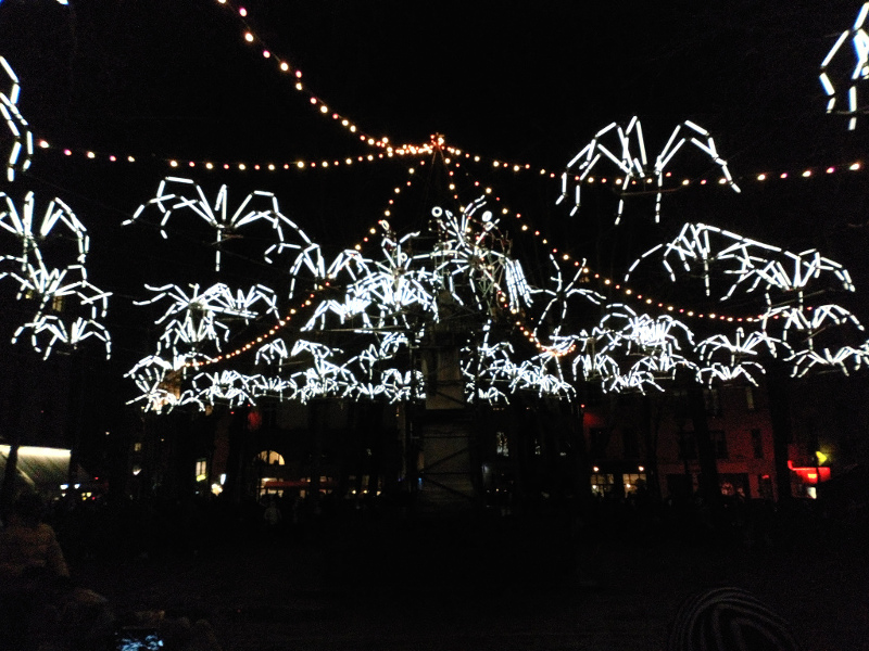
Back on August 28th, have a good holiday and mind the spiders!
June 30 2017
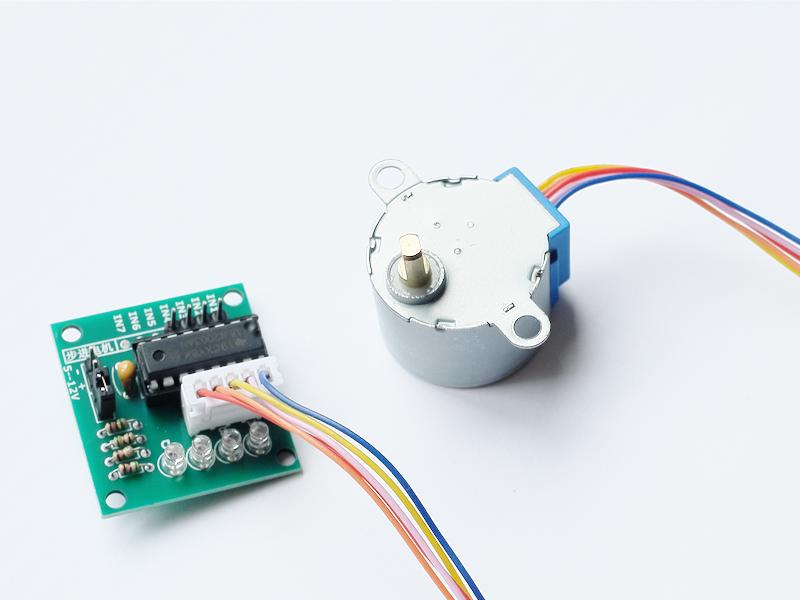
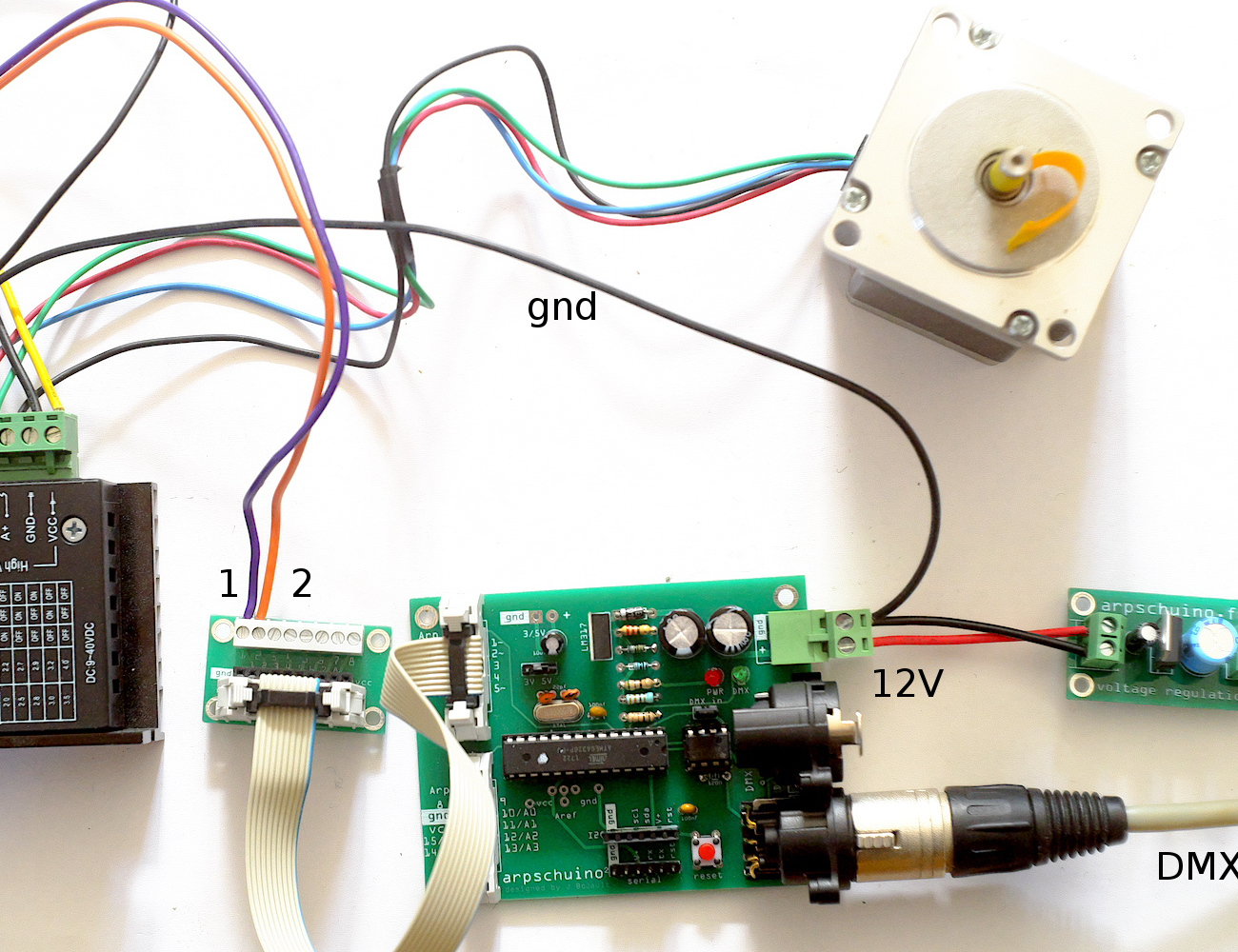
A little tutorial for this summer ?
Learn how to drive a stepper motor by DMX with an arpschuino.
June 19 2017
On June 24th do not miss Exit, the last show of the Cirque Inextremiste, at the park of Sceaux in Antony (near Paris).

Arpschuino will be there, we are testing the new wilulus. The opportunity to meet?
Then, the summer tour in Nantes, Mulhouse, Aurillac, St Agil et Cergy.
Cirque Inextremiste news
may 11 2017
The tutorial "starting a ballast in DMX" now in english.
april 9 2017
In response to several requests, here is a new tutorial: Program an arpschuino.
To simply reprogram the arpschuino according to your needs, using the source codes available on the download page, modifying them or writing yours.
If something seems unclear, please let us know.
february 27 2017
2 years !
arpschuino.fr is 2 years old today.
To celebrate this, no less than 2 new boards:
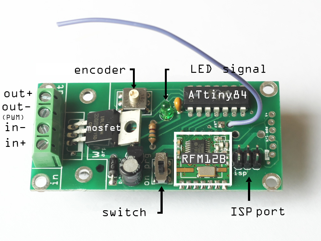
The arpsensorsRF and the arpRF, both equipped with radio module RFM12B.
All the functions of arpsensors and arpschuino are now available with a radio link.
As usual, do not hesitate to contact us to tell us about your project, ask us questions.
january 11 2017
the drilling of the boxes may be imprecise...
This template may help you :
It is available in download page.
If you print it, don't forget to check the actual size option.
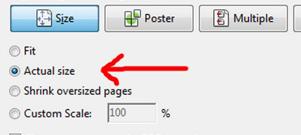
You can then use the print to point before drilling.
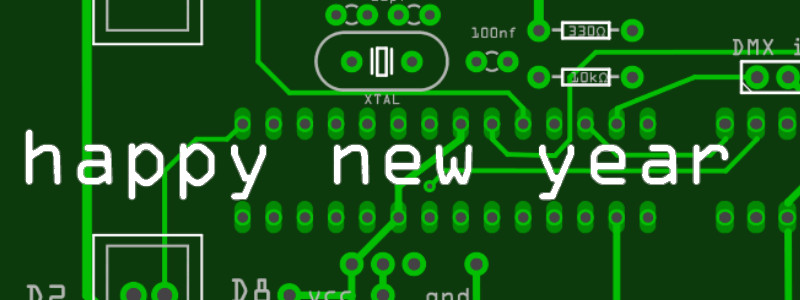
January the first 2017
We wish you an :
december 27 2016
After our first tutorial, Driving a 8 relays board by DMX, here the suite,
starting a ballast in DMX, it's a practical application.
Sorry it's only in french for the moment...
Thanks to Philippe Bouttier from Surnatural Orchestra.
december 15 2016
The website has been redesigned, with now drop-down menus for easier navigation.
In the example section you can discover the last show of the company 1-0-1: Haraka.
A new links page has been created, and a new FAQ.
For now it's only an embryo of FAQ, it's up to you to make it grow by asking questions on arpschuino@gmx.fr
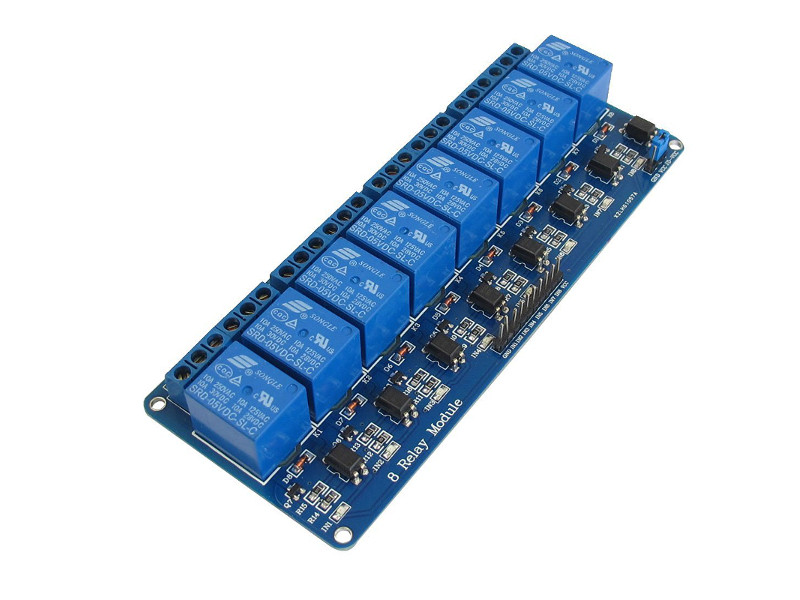
november 20 2016
here it is, our first tutorial, Driving a 8 relays board by DMX, is online.
Probably the first of a long series, tell us what is your interests:
arpschuino@gmx.fr
november 10 2016
It's fall ! Walking in the woods can be strange discoveries:
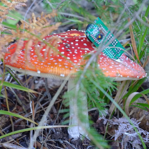
A new board in peparation ? To be continued...
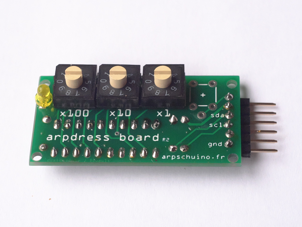
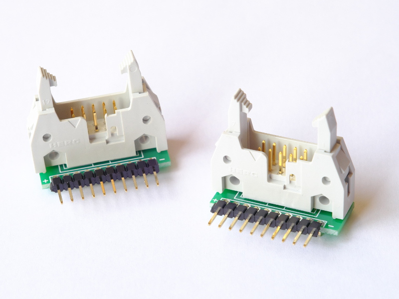
October 23 2016
The new PCB for the arpdress board has been made to mount the rotary encoders in the opposite side of the componants.
It will be easier to put it on a box, we can now also deport the reset button of the arpschuino.
After being hosted for a year and a half by the company 1-0-1 (pschuuu, perturbations),
arpschuino is now an association "law 1901", the french denomination for non profit association.
To call us, it's always arpschuino@gmx.fr
September 26 2016
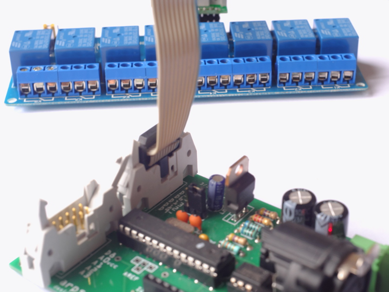
Here is a new adapter for arpschuino :
The arp>breadboard adapter allow to connect arpschuino (or apower), not only to a breadboard, but with many type of devices.
A small board which should enjoy hackers and prototypes makers !
It allow, for example, to drive a
8 relays board in DMX, with arpschuino.
May be an opportunity to do a little tutorial on it?
If you have ideas for tutorials, please submit !
August 16 2016
Soon the rentée!

Arpschuino.fr is now opens and resumes its activities.
See you soon...
June 28 2016
I will be in Avignon from 4 to 8 July. Perhaps the opportunity to meet?
User or simply curious, feel free to contact me: arpschuino@gmx.fr
The website will be closed from 22 July to 13 August. Happy holidays!
June 23 2016
A new PCB for the arpower :
The features do not change but the connectors are flat now, the fixing holes have been enlarged and the serigraphy have been improved.
the arpower's assembly guide have been revised for the occasion.
may 05 2016
Arpschuino's source codes have been revised:
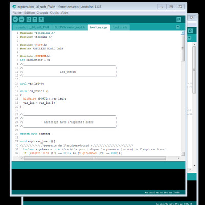
They are available on the download page
The features do not change but the functions (for signal LED and adressing) are now in separate files.
This should improve the readability of source code and allow, for those who want to reprogram the arpschuino, to edit more easily.
I tried to comment to make it as comprehensible as possible but but do not hesitate to contact us for more information :
arpschuino@gmx.fr
mars 26 2016
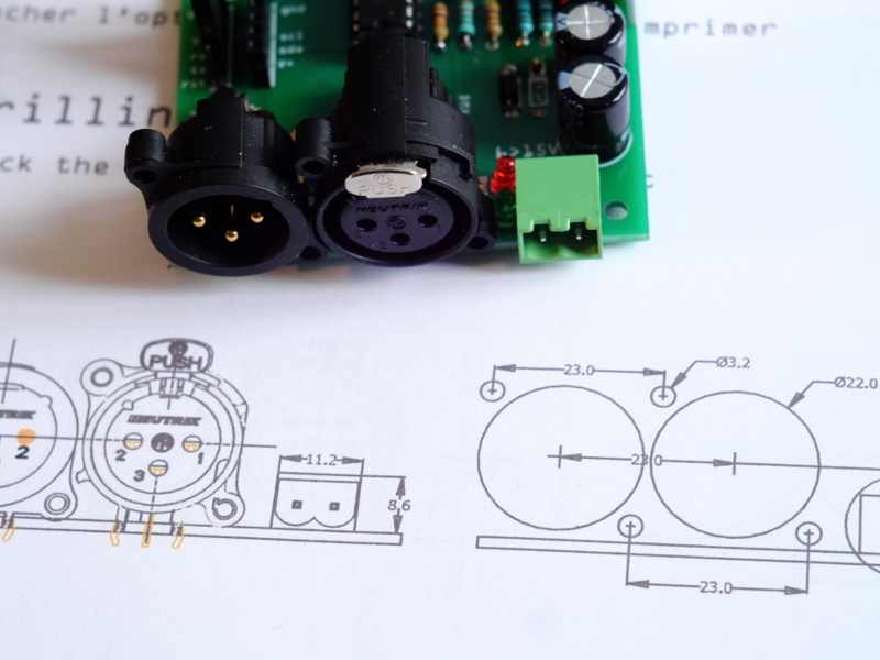
This is an XLR version of the arpschuino² :
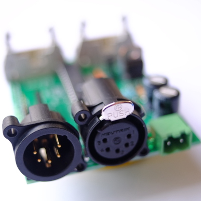
XLR can come in 3 or 5 pins. Classicals green connectors are still available.
The new PCB allows to choose one of these three options.
For those who prefer one with a remote connection, we also offer new XLR adapter on PCB:
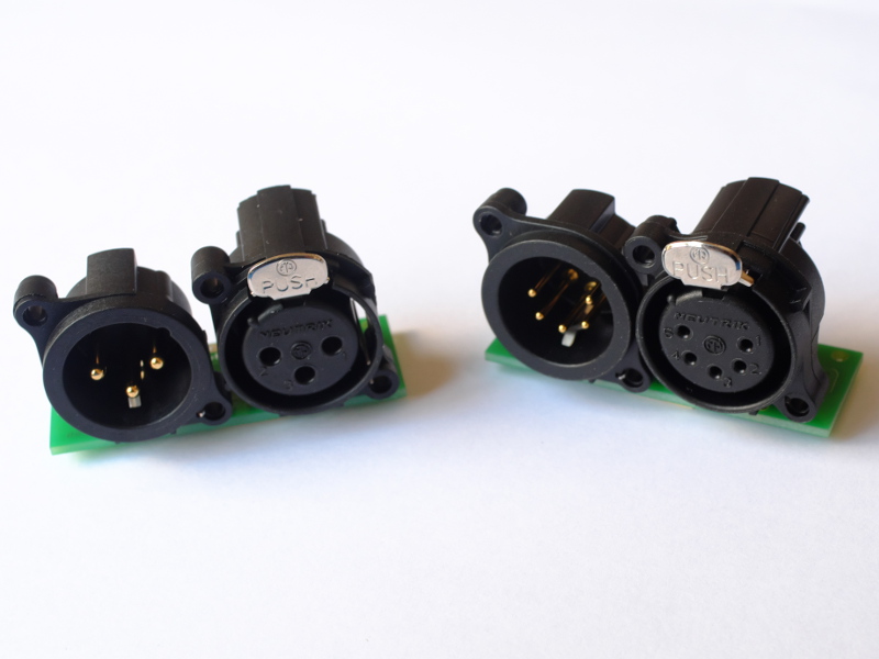
The metalics ones are still available.
thank to Eric Julou for his decisive help.
mars 10 2016
Here's something new for JeeNode's users:
The JeeNode>arpower adapter plugs directly into the JeeNode to provide the control of the 8 arpower 's outputs (2 or 8 amps!) ..
Several example sketchs are provided and we are always there to answer your questions on arpschuino@gmx.fr.
Other adapters are coming soon ...
february 27 2016
One year !
There's just one year, arpschuino.fr appeared on the web.
We wish it a happy birthday and thank you to everyone who helped, supported and trusted us
february 01 2016
January in the Caribbean ...

During the pschuuu tour on the Caribbean, we provided a training in Fort de France.
6 days have been dedicated to "Arduino and electronics for stage", provided by Jacques Boüault.
4 other days was dedicated to the VVVV software, provided by Christoph Guillermet.
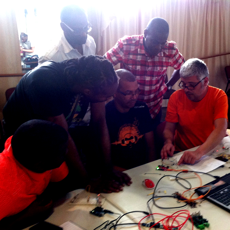
I take this opportunity to greet all parrticipants, and to thank them for their attention, motivation and patience.
If you want to organize this type of training, please contact us : arpschuino@gmx.fr
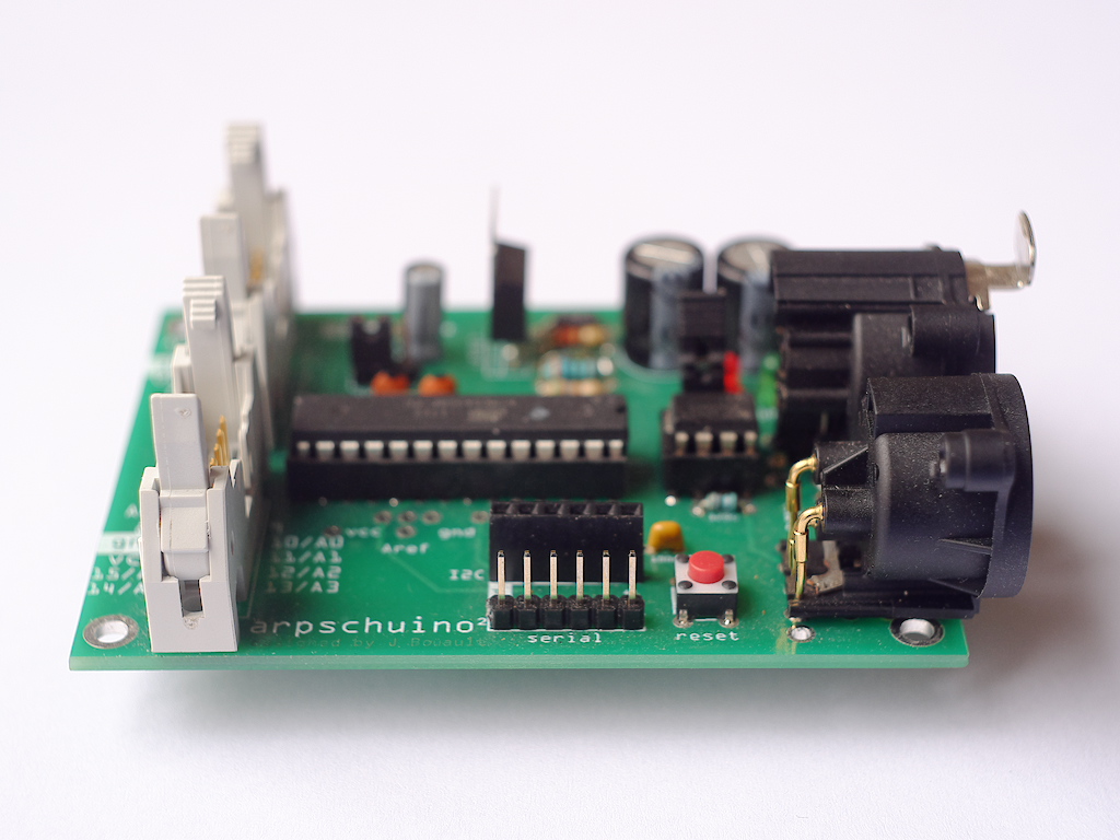
november 18 2015
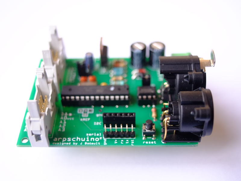
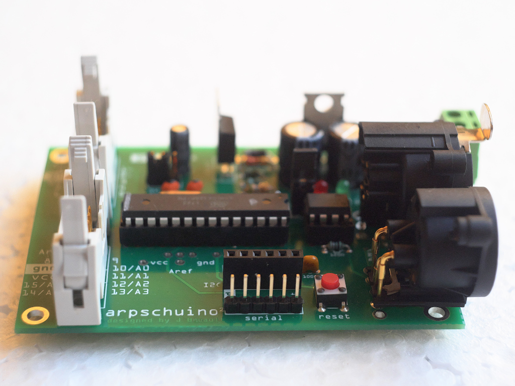
Here is the arpschuino² :
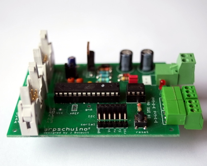
This is the new version of arpschuino, it replaces the "classic" arpschuino while remaining fully compatible.
Devices can be powered now more easily by arpschuino², in 5V or 3.3V. It will allow many evolutions for exemple with an RF link in preparation (to be continued...).
Other improvements have been made, all the details are here.
Good news, the arpschuino² remains at the same price as the arpschuino !
As usual, we are at your disposal to help you and answer your questions: arpschuino@gmx.fr
october 28 2015
Announced from a long time, there it is, the arpsensors is online :
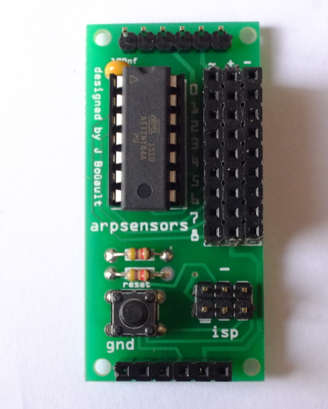
This small Attiny84 based board receives and processes (smoothing), data from analog sensors.
A example code of reception and monitoring on the serial port is available on the downloads page. other examples are coming.
The arpsensors is reprogramable via its ISP.
If you have any questions please ask us by mail: arpschuino@gmx.fr
octobrer 02 2015
The arpschuino user guide is now(at last !) online.
After many requests, we now offer small amounts of thermal paste (1g), it is enough to assemble an arpower. Here.
Pschuuu on stage again, all the dates here.
august 02 2015
End of holidays for us !

arpschuino.fr resumes activitées and remains open during August.
June 24. 2015
arpschuino.fr takes its Holiday in July.
If you want to order a card that is until June 30, or from 1 August.
New in this update:
An user guide for the grada laps in French and in English.
The assembly guide of arpschuino is now bilingual .
Happy holidays.
June 15. 2015
It's called arpsensors :
L'idée est de est de relier divers capteurs analogiques à un arpschuino ou autre (arduino, jeeNode...).
Il embarque un petit microcontrôleur (Attiny84) chargé d'un pré-traitement, d'un lissage des données et de renvoyer les informations via une liaison I2C.
Il est actuellement en phase de tests dans le cadre du travail pour Perturbation, le prochain spectacle de la compagnie 1-0-1 (Pschuuu!).
En avant première une vidéo des dernieres avancées, avec le grand jet piloté par divers capteur sur le corps.
Lorsque l'arpsensors sera suffisament testé et éprouvé, nous vous la proposerons sur ce site
Si ça vous intéresse et si vous voulez plus d'infos, n'hésitez pas à nous écrire : arpschuino@gmx.fr .
May 23. 2015
Soon new item !
To be continued ...
April 3. 2015
Now in english !
This website now has an English version. Please if it is your native langage be indulgent, there probably still many errors and approximations.
If you see some errors please let us know by email (arpschuino@gmx.fr).
13 mars 2015
Pschuuu reprend la route !
Si vous êtes en Bretagne, Normandie, Ile de France ou en région lyonnaise, ne ratez pas l'occasion.
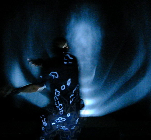
En particulier, le 2 avril, en avant première, une étape de travail de la forme performance en live avec le musicien Fred Duzan.
Au programme, de nouveaux jets solos de 3,5m, pilotés par gesture depuis le plateau
On espère vous y voir, faites vous connaitre.
Toutes les infos ici
27 février 2015
le site arpschuino.fr fait son arrivée sur la toile.
Il est encore en construction et encore loin d'être fonctionnel.
Le matériel que nous présentons est lui en revanche parfaitement fonctionnel!
Si vous êtes intéressé n'hésitez pas à nous contacter par mail pour l'instant.
N'hésitez pas non plus à nous écrire pour nous poser des questions, nous faire part de vos commentaires ou de vos demandes.